Hi Magura,
How would the quality of it affect the CLC filter?
Next, actually my plan is 4mH-->44mF-->0.1ohm-->40mF,will this avoid some of the problems mentioned earlier?
The quality of the wire, is a matter of the quality of the enamel. How uniform the layer thickness is, and how many holes there is in the enamel.
There are standards for these things, but some manufacturers barely make it to the lowest standard, while others exceed the highest.
How this influences to an inductor:
1) Safety margin
2) Lifespan
3) How well the impregnation adheres the the enamel
4) Max. permitted temperature (power handling).
The above factors, will influence vibrations, and noise as well.
When I make inductors for my amps, I always buy the best possible quality of magnet wire, as it makes no real difference, if I pay 10$ per kg, or 15-20$ per kg.
What does make a difference to me, is if I have a dependable inductor, which makes no noise.
As for your planned filter, I'd stick to a 2mH CLC. If you want to get better performance, get bigger and better caps (Rifa PEH169 for instance), and spice the whole thing up with a couple of hefty film caps.
Some 50 to 150uF of PP film right before the amp will do.
Magura 🙂
> BTW what amp is it??
We have the same generic tower design for different amps, all class A. They include 100W AX, JLH-X Mosfet, 2x 35W Circlotron (with NFB) and active crossover for a 2-way speaker, my yet-to-be-build Circlotron with zero global FB, and a mini-version (70% linear shrink) for F5 & AX-30W.
> Puts the origin to shame, doesn't it.
That is the first time I heard anything from you that sounds remotely like a complement....
😉
And no, I cannot supply them for US$140.
Just the two heatsinks without machining and anodising cost more than that.
Mr. Levinson had to make a profit, so he had to make compromises. I don't.
We are lucky to have access to good machining facilities.
Just ask the guys from the dual jfet heatsink GB ......
Patrick
Could you make such a case or one similar available for purchase?
Russellc

Hi,
should we really be using a lateral FET (low Vgs) for the cascode devices?
Would a lower power Vfet be better as a cascode? Maybe a 510 or 610
should we really be using a lateral FET (low Vgs) for the cascode devices?
Would a lower power Vfet be better as a cascode? Maybe a 510 or 610
You meant something like the original circuit?It will work if you first create a 0 volts point using serial connected caps such as in the Quad arrangement,
The quality of the wire, is a matter of the quality of the enamel..............
Some 50 to 150uF of PP film right before the amp will do.
Magura 🙂
Thanks Magura.
Hi,
should we really be using a lateral FET (low Vgs) for the cascode devices?
Would a lower power Vfet be better as a cascode? Maybe a 510 or 610
Probably
I really don't know enough.
So far it has been a process of trial and error, and the laterals look the best so far.
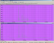
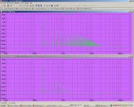
Standard vs Cascoded
The results are for 2.8V pk output into 8 Ohm load at 1000Hz.
The top fft is the standard version, the bottom fft is the cascoded version.
There is almost a 20dB improvement on both 2nd Harmonic and 3rd Harmonic peaks with the cascoded version, compared to the standard
The results are for 2.8V pk output into 8 Ohm load at 1000Hz.
The top fft is the standard version, the bottom fft is the cascoded version.
There is almost a 20dB improvement on both 2nd Harmonic and 3rd Harmonic peaks with the cascoded version, compared to the standard
Attachments

Last edited:
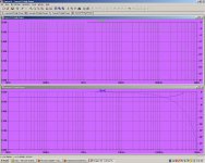
Just in case there is any doubt the next one is 20V pk out into 8 ohms at 1000 Hz.
Top of screen is standard version, bottom of screen is cascoded version.
Interesting plots! Can you show us the frequency response too? It would be sad if the effects we are seeing are just due to shifted low pass pole... 😉
You meant something like the original circuit?
Look at the 606 psu
http://quad405.com/606schematic.pdf
You have to add a cap across 48v. This is class A
See post 4239 p424 .
Here is a cascoded version happily running with 40 V rails
It simulates quite nicely too.
I can post some results if anyone is interested.
Wow, thats fantastic
Nelson did suggest to try that a week or two ago
😎
Hi,
should we really be using a lateral FET (low Vgs) for the cascode devices?
Would a lower power Vfet be better as a cascode? Maybe a 510 or 610
Hmmmm, the lateral MOSFETs have gm on the order of unity...
Russel, the Tech-diy kits are avaiable with the Fairchild FQA12P20 and FQA19N20C MOSFET's. I received these within the last couple of weeks.
I ordered the kit with the IRF devices, but also ordered the Fairchild devices seperately to try. My mosfets will be on short leads, so changing out may not be a problem. My guess is, the IRFs will never leave unless they dont work....hardly likely Id think.
russellc
Note that the mounting hole for the Fairchild devices seems designed for a metric screw. I have drilled it out to accommodate US/UK screw sizes without ill effect.
I also received some TO-220 analogs to the TO-247's which are now difficult to source. Hopefully I can test these in the next couple of weeks.
By the way, the US Post Office just reported this morning that they had a software meltdown for package tracking in the US. Most packages mailed from October 1st this year can't be tracked.
- Home
- Amplifiers
- Pass Labs
- F5 power amplifier