Hey guys,
I'm planning to use an inductor in the supply. I know there have been several posts regarding this approach. Any ideas on what to use? Part numbers?
About 2mH, and large guage, yes?
Thanks!
though normal tube amp chokes are made for high voltage and low current
if presented with lower voltage only, maybe they will do higher current
but I dont know
maybe Hammond "reactors"
http://www.hammondmfg.com/195.htm
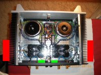
some parts of the heatsink measure as high as 67º. I get .520v across the source resistors.
Get bigger heat sinks or get a fan on it.
Thanks, how about this:
Hammond Mfg. - D.C. Filter Chokes - (153 - 159 Series)
Part 156B: 1.5mH, 5A. Two of these, one each for the positive and negative rail.
Hammond Mfg. - D.C. Filter Chokes - (153 - 159 Series)
Part 156B: 1.5mH, 5A. Two of these, one each for the positive and negative rail.
The enclosure is already finished and everything already assembled, I'm afraid getting bigger heatsinks is not an option.Get bigger heat sinks or get a fan on it.
Maybe I can manage to fit a pair of small fans to exhaust some air, but not direct on top of the fins, but inside the case pulling air out. But I don't really like the idea, I will try to get bias even lower.
some data for my ancient Iskra DC chokes (originally from movie theater projector ; presumably 9mH, certainly 0E2 Rdc) :
EI72 package
height of package ~30mm
entire window filled with 1,25 enameled wire
air gap ~ 0,5 mm
EI72 package
height of package ~30mm
entire window filled with 1,25 enameled wire
air gap ~ 0,5 mm
Now, can the choke go before the first cap after the rectifier.... I've read that this helps slow down the charging of the capacitors.
Regi
If you have some very small computer fans lying around... Try a 9V battery and a pot on them. You can vary the speed this way. You might simply prop them up on the carpet near the heatsink and see if you can get away with a super small fan with a very low speed. Basically just giving a slight breeze to keep the air moving. Then you can permanently install later but I am betting you need only a slight breeze to keep them in the right temp range.
Uriah
Is it a better option to use bigger fans if being placed on the outside. They need far less rpm to move the same amount of air compared to an small one. I am thinking in attaching as in the picture (red ones)Regi
If you have some very small computer fans lying around... Try a 9V battery and a pot on them. You can vary the speed this way. You might simply prop them up on the carpet near the heatsink and see if you can get away with a super small fan with a very low speed. Basically just giving a slight breeze to keep the air moving. Then you can permanently install later but I am betting you need only a slight breeze to keep them in the right temp range.
Uriah
Or maybe placing two small as like the green ones.
Regards,
Regi
Edit: Wrong picture, now it's ok.😎
Attachments
Hey
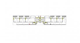
I have been trying to do a layout for F5 with hard wired output
with cascode input, yes
Nelson was the first to suggest cascoded, so why not 😛
Then, when I looked at my Jfet board, I suddenly realised how easy it would be to implement the outputs into the board, if one should wish so
and when trying to actually draw the thing, a new thing suddenly popped up
a board with any number of multiple outputs
just hack off the ones you dont want
so far its just in the principle stage
but is it worth something ?
and btw, a happy new year to all
Attachments
just hack off the ones you dont want
I usually put my multiple output drivers along one edge and that way I can or not use any ones I want without using up a lot of pcb real estate.
How many output pairs can the input JFETS realistically drive?
Is 2 pairs the maximum, or 3 or 4?
Is 2 pairs the maximum, or 3 or 4?
Fans = noise.
I think we discussed this a few hundred or more posts back...
Centrifugal blowers are quieter, especially when larger ones are run at slower speeds... and they work into back pressure, rotary fans don't do that well... fwiw.
_-_-bear
PS. Thermite really permits a very high instantaneous "DC" output... 😛
How many output pairs can the input JFETS realistically drive?
Is 2 pairs the maximum, or 3 or 4?
on thin ice here 😱😛
but I dont think the Jfet is a driver, as such
outputs are driven by their own transconductance, and high classA bias
ideal is one pair
realisticly you can use two pair
I think the problem is partly input capacitance
it doubles with double devices, etc
and you may need to double the bias current, or close
I dont know about the Toshiba outputs
but the original, as per manual, should be tough devices
I reckon one pair should be able to do 35watt or so, with cascoded Jfet
but heatsinks needs to huge
double heatsinks, and mono's only
whether its worth the trouble, I dont know
enough parts to do 2x stereo instead
but I also have to think about my electricity bill as well
They need far less rpm to move the same amount of air compared to an small one.
Most noise is generated at the tip of the blades (identical to ship screw blades)
The bigger the fan, the larger the blades, the higher the efficiency.
Bigger fan with lower rpm : same air flow with lower noise level.
Most noise is generated at the tip of the blades (identical to ship screw blades)
The bigger the fan, the larger the blades, the higher the efficiency.
Bigger fan with lower rpm : same air flow with lower noise level.
I think I would mount a micro fan in a tube, blowing directly on the devices, inside
with ordinary heatsink ribbing, I dont see a fan being very optimal
its disturbing the natural convection flow
I reckon there would quite some gain from lowering temperature inside the box
It's not an F5, but JimT's cascoded BA-2, drives 6 pairs of devices at around 50v.
If you have inefficient speaks, or big 15" drivers, think about that.
If you have inefficient speaks, or big 15" drivers, think about that.
Most noise is generated at the tip of the blades (identical to ship screw blades)
Yeah, i think we need caterpillars as in "The Hunt for Red October" -- no cavitation!
- Home
- Amplifiers
- Pass Labs
- F5 power amplifier