One channel of the Hitachi/F5 has been up and running since this afternoon.
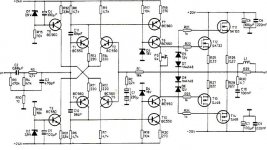
Circuit same as F5 only with 2sk134 & 2sj49.
Biased up very easily to 1.24amps and >1mv offset which has not varied over a four hour period.
Taking this short break before heading back to wire in the +-G to the second channel.
Playing a Philips CD80 single crown dac w/ mod'd op amp outputs. BUF03 for the output buffer, I think the I/V is done with an AD797 if I recall. Running directly into the F5/H as the CD80 has variable outputs. Playing thru an old Maggie II.
I've got the mosfets on the paddle-wheel heatsink from the Old Colony Borbely B60 kit. I'm surprised it's running as cool as it is!
If this sounds good and behaves I'll switch the outputs over to the DC100's
which has three pair 2sj56/2sk176 per channel.😀
Hi Ichiban,
Are you using a single pair or more?
Hi Ichiban,
Are you using a single pair or more?
Currently using one pair of 2sk134 & 2sj49 as a test
before exposing expensive/obsolete three pair 2sj56/2sk176 per channel.
By the way the single pair is sounding fine 😀
seems to reveal a little more low level
detail and tighter images, compared to the Fairchilds.
Won't be trying the 3 pair/channel until the
weekend at the earliest.
I'll be using Borbelys method to suppress ocillations
and the one gate resistor on the CVillar board and another
at each gate.
I was referring to drift during power-up. Once at steady state, it was very stable.
The Xed-F5 does have some DC feedback, so it is not anywhere as bad as the AX during warm up. The drift will be worse with Fairchild devices (as they are in the SE version). But I still recommend loading each of the outputs to ground with say 33R 50W.
Hi Patrick,
just after power-on the absolute offset amounts to ~70mV and decreases during power-up phase to ~10mV. The differential offset wanders during power-up from ~10mV to ~1mV.
Perhaps you could also commend on the sonic difference between grounded and floating X. For me, the difference was not significant. But I have not been listening for long, and also it was a long time ago.
This evening I found some time for a short listening test. I started with the grounded X. The next test was with the shorted (but not grounded) X. The last configuration I've listened to was your X topology (my standard setup).
In my opinion there is a difference between the sound of the grounded and floating X. The first one sounds a bit harsher, also the resolution is a bit poorer. My subjective impression: the floating X configuration sounds a bit better then the grounded topology. Between the two floating X configurations I couldn't hear any significant differences. Maybe I need more time for listening and much better speakers ... 😉
For the listening session I've used the following recordings:
Ry Cooder: Paris, Texas (original motion picture soundtrack)
Diana Krall: The Girl In The Other Room
Barb Jungr: Every Grain Of Sand
Patricia Barber: The Cole Porter Mix
Here is my current listening setup:
post #5673
Regards, Uwe
PS:
Sorry for the late reply.
Currently using one pair of 2sk134 & 2sj49 as a test
before exposing expensive/obsolete three pair 2sj56/2sk176 per channel.
By the way the single pair is sounding fine 😀
seems to reveal a little more low level
detail and tighter images, compared to the Fairchilds.
Won't be trying the 3 pair/channel until the
weekend at the earliest.
I'll be using Borbelys method to suppress ocillations
and the one gate resistor on the CVillar board and another
at each gate.
You aren't kidding, ampslab has the 2sj56/2sk176 for $60/pair!
So, you'll have a gate resistor on each mosfet plus one on the board being shared? Please post a picture when it's done.🙂
You aren't kidding, ampslab has the 2sj56/2sk176 for $60/pair!
So, you'll have a gate resistor on each mosfet plus one on the board being shared? Please post a picture when it's done.🙂
A good reason to stick to readily available MOSFET's
IRFP's are about £1-50 at my stockist.
46N15's are about £1-23 each for 250W.
Currently using one pair of 2sk134 & 2sj49 as a test
Even the 20W Class A Lateral Mosfet amp by K. Lang did not have that feature.
That thingus was biased to 2A btw, aka 32W rms Full Class A in 4 Ohm.
AudioXpress should still sell boards for the amp, the design appeared in audio/radio mags all across the globe mid 1980.
[and for the ones who still don't get the jokey after two decades and spare change : the author K. Lang stands for "Klang", which is the German word for "Sound" ]
The fun of evolution is how much better something can sound with fewer parts 25 years down the road, there's progress for ya.
Wasn't it Borbely who put 300pF caps across each gate of the N-channels to level out the input capacitance on both sides ?
Attachments
Last edited:
si es para un amplificador de auto... lo que pasa es q yo se arreglarlas pero necesesito saber cuales son los q lleva.... no se donde conseguir el diagrama electrico.... sound storm f4-1600 4 canales
The fun of evolution is how much better something can sound with fewer parts 25 years down the road, there's progress for ya.
Not to forget Le Monstre 1983
Joselito,
This is an English speaking forum. If you wish to post in another language please also post in English
This is an English speaking forum. If you wish to post in another language please also post in English
Member
Joined 2002
F 5 is working 🙂 thank you Mr.nelson for sharing your knowlege.First impression if i compare with phase linear 700b -warmer sound,lower bass,20 w is more than enough for normal listening.
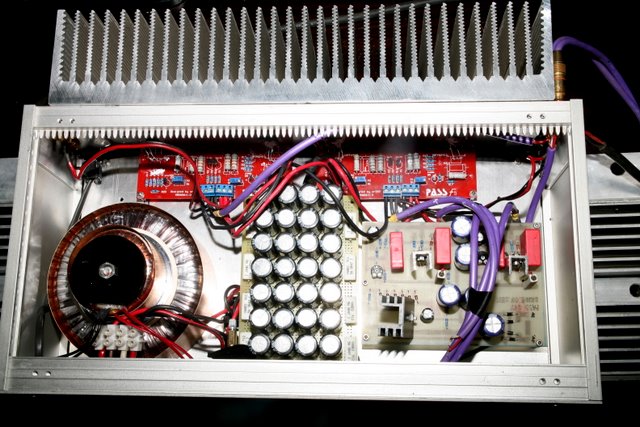
Are those pass labs clone boards from ebay or something ? ( the red boards )
Even the 20W Class A Lateral Mosfet amp by K. Lang did not have that feature.
That thingus was biased to 2A btw, aka 32W rms Full Class A in 4 Ohm.
AudioXpress should still sell boards for the amp, the design appeared in audio/radio mags all across the globe mid 1980 ....................
Wasn't it Borbely who put 300pF caps across each gate of the N-channels to level out the input capacitance on both sides ?
I have that issue of Audio Amateur #2 1986 page 7, 'The Lang 20W Class-A Mosfet Amplifier'. Pulled it out last Friday to see how high he biased it. He has two pair per channel at a quiescent current of 2 amps with a supply voltage of +-20volts.
I've got 330pFs on each 2sk176 (in the Borbely DC100). I still had oscillation, it drove me nuts, until while poking around with a grounded wire, I finally discovered that grounding the heatsink the driver mosfets on the PC board were mounted on killed the oscillations.😎
Last edited:
You aren't kidding, ampslab has the 2sj56/2sk176 for $60/pair!
So, you'll have a gate resistor on each mosfet plus one on the board being shared? Please post a picture when it's done.🙂
Bought matched sets from Bear Labs N.Y. late 1980's. Don't recall what I paid.
Yes, the onboard resistor and one at the gate of each mosfet. I don't recall where I read it, someone who works with high frequency circuits wrote that it was used to prevent osc.
Will take some pics of the F5/DC100 cobble, when done.
Did more listening this evening and I'm finding very nice. I have it scabbed onto one of the F5s(dual mono) power supplies. I should rewire the F5 into a single ps then I could switch amps easily to compare. Audio memory being as they say not so reliable. But, I'd bet on the Hitachi output winning this one.
Just in update (if anyone is curious) on my problem. It was most likely my output mosfets. I changed out everything that I thought could be the cause, with out any change. I'm guessing that it my heatsinks that I fabricated together. I mounted three
heatsinks (each 4X6 with 2inch fins) on a 1/2inch thick aluminium bar. I don't think they were completely flat causing pockets. So hopefully that was it. I also added some small heatsinks directly on top of the mosfets when mounting them. The little guys get hot.
heatsinks (each 4X6 with 2inch fins) on a 1/2inch thick aluminium bar. I don't think they were completely flat causing pockets. So hopefully that was it. I also added some small heatsinks directly on top of the mosfets when mounting them. The little guys get hot.
I still had oscillation, it drove me nuts, until while poking around with a grounded wire, I finally discovered that grounding the heatsink the driver mosfets on the PC board were mounted on killed the oscillations.😎
A fine example of the value of poking around. When you
get oscillation, you arm yourself with some clip leads,
capacitors, resistors, and a couple hours.
😎
Member
Joined 2002
Uwe,
I would agree with your impression that there is a difference between floating X and grounded, but in my case the difference is small. It may have to do with our circuit differences. The drift figures are similar to mine.
I have already explained in detail before why I chose the Toshiba MOSFETs (with measurements to support). I am not going to repeat that again.
😉
Patrick
Member
Joined 2002
Do you mean like rip-offs of copies of clones?
😎
Looks like some clone!
hello for all,
I started to worry (little) about my heatsink size for F5 when looking at these large on pictures above . Your opinion on my radiators- ? The size is 12x5x1 inches or 29x12x2,5 in cm. will be fine ? enclosure is almost finished and PCB also etched and soldered.🙁 My enclosure in attachment.
Thanks and regards.
Attachments
hello for all,
I started to worry (little) about my heatsink size for F5 when looking at these large on pictures above . Your opinion on my radiators- ? The size is 12x5x1 inches or 29x12x2,5 in cm. will be fine ? enclosure is almost finished and PCB also etched and soldered.🙁 My enclosure in attachment.
Thanks and regards.
it will be OK ;
one mistake - you must ventilate that box ;
you need some holes on bottom and top plate , or you'll cook all caps and blablah .
doesn't matter what size heatsinks are , air is a must for electronic in this case
- Home
- Amplifiers
- Pass Labs
- F5 power amplifier