The sink does get sligtly warmer now than before,The offset and Bias(1,3A)is spot on.How can it then get hotter?
It sounds fine,no distortion.
I was referring to the resistors that fell out of the board - this may have been due to the resistors cooking more than what good was. I'm not sure how plausible it is, but if the resistors R11 and R12 were off (too high) resistance it could have caused them to heat up more while playing music and at the same time having less dissipation on the heat sink.
Another thing and probably more plausible could be incorrect adjustment.
How far did you match the two sides of the X?
Only the JFETs regarding Idss, if I recall correctly something around Delta_Idss = 100uA (Idss ~ 10mA). And the MOSFET source resistors and feedback resistors. All other resistors are of 0.1%.
Uwe
Hello
Guys when I understand the advise clearly of course I take it , I would be crazy not to do that .
Especially from JUMA who was always so helpful . I have BL , and GR grade JET , now days hard to find these JETs .Especially in V grade (and enough parts to match them for 4 board) . I have to stick with the BL grade .
Juma I take your advise and I use 4k7 resistor to feed the BJT and 2k7 frome base to the ground .
Next time if I'm tired ( I didn't slept more than 24 hours) I do not ask for help .It will be no more misunderstanding .
I hope you can forgive me !
Thanh we always used the word JET (probably wrong to do that) not jFET --- that is why I got confused !
Now I slept I see different way all and clear to me .
generg thank you !
Thank you one more time guys , no more question "just hands on" !!
Greets
Last edited:
> I hadn't any problems with increased DC offset drift (neither absolute nor differential) beside the well known absolute offset drift after power on (during heating). Right now the absolute offset is something around 10mV and the differential offset is around 1mV for both channels.
I was referring to drift during power-up. Once at steady state, it was very stable.
The Xed-F5 does have some DC feedback, so it is not anywhere as bad as the AX during warm up. The drift will be worse with Fairchild devices (as they are in the SE version). But I still recommend loading each of the outputs to ground with say 33R 50W.
Perhaps you could also commend on the sonic difference between grounded and floating X. For me, the difference was not significant. But I have not been listening for long, and also it was a long time ago.
Patrick
Now you are at it, regarding cascode connection
We have had two variations
One with base resistor/cap connected directly to Jfet
Other variation connected directly to ground
Nelson clearly stated that probably somewhere in between
Or that it would be best to try it out, what to choose
And what really makes the difference
Certainly not the present 10R ground resistor, at least I guess not
So, it must be the direct connection to Jfet that might be critical
Is it the 2K7 or maybe the cap
I have decided to replace the original 10R ground resistor with 3x 5R resistors
They are ofcourse individually adjustable
Maybe a trim pot might work too, maybe just in paralel with resistor to fine adjust
Just my thoughts about it
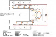
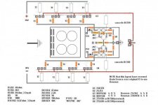
Please read #NOTE#, pinout is changed to use lateral Renesas
We have had two variations
One with base resistor/cap connected directly to Jfet
Other variation connected directly to ground
Nelson clearly stated that probably somewhere in between
Or that it would be best to try it out, what to choose
And what really makes the difference
Certainly not the present 10R ground resistor, at least I guess not
So, it must be the direct connection to Jfet that might be critical
Is it the 2K7 or maybe the cap
I have decided to replace the original 10R ground resistor with 3x 5R resistors
They are ofcourse individually adjustable
Maybe a trim pot might work too, maybe just in paralel with resistor to fine adjust
Just my thoughts about it
Please read #NOTE#, pinout is changed to use lateral Renesas
Attachments
Last edited:
---
I have never seen a Mega Farad but I would not enjoy crashing into it with my car (automobile).
I think a Mega Farad is the thing that lives in the Loch Ness.

If you really have to cascode, why not just use a simple JFET as cascode, a la Borbely?
You can use J111 / J174 for that purpose. Will give you 5V Vds across the Toshibas at about 6mA Id.
Patrick
You can use J111 / J174 for that purpose. Will give you 5V Vds across the Toshibas at about 6mA Id.
Patrick
Thank EUVL
Good idea , I have to take a look if I found something at Mr Borbely site .
Thanks one more time .
I'd like advise like yours , you do not write to me just give it up !
Always helpful.
Greets
Good idea , I have to take a look if I found something at Mr Borbely site .
Thanks one more time .
I'd like advise like yours , you do not write to me just give it up !
Always helpful.
Greets
http://www.borbelyaudio.com/adobe/ae699bor.pdf
Fig.17, Q3, Q4.
The devices he uses will NOT do. Idss too low, giving only 2V Vds on the K170/J74.
Patrick
Fig.17, Q3, Q4.
The devices he uses will NOT do. Idss too low, giving only 2V Vds on the K170/J74.
Patrick
I used 2sk246 and 2sj103, but that was meant to be my secret.
Too late now.
There is a trick though to get them to work properly in the F5 circuit. Let's see if Patrick can figure it out.
Too late now.
There is a trick though to get them to work properly in the F5 circuit. Let's see if Patrick can figure it out.
Hi Gaborbela
I really enjoyed some of your recent posts. You had a lot of people close to pulling their hair out. It was a lot of fun.
If anyone deserved a Gomer Pyle award, you would have to be a strong contender for some of the those last few posts.
They were absolute classics.
Anyway keep going with this, you will get there in the end.
The only advice I would add here, is it is time to start building.
Sometime it is not possible to see all the problems you might experience until you start building. So start building, there are enough people here to help you out along the way.
The sooner you start the sooner you finish.
I used 2sk246 and 2sj103, but that was meant to be my secret.
Too late now.
There is a trick though to get them to work properly in the F5 circuit. Let's see if Patrick can figure it out.
Hello Thanh
I'm interested about the 2SK246 & 2SJ103 if you use them as a cascode .
Patrick gave me a great advise but hard to find parts unfortunately ....At least I look on the Ebay and not one piece I sow.
Or if is so much secret and you want to keep for yourself it it is not a problem .I do not get upset NEVER on those people who willing to help with out criticise my plan .
Give it up ! And so on it make me to act like these especially if I'm tired .
Even you wrote before Andrew not very helpful sometimes even do he has the knowledge and great ideas.
Yes he tried to help me but the way he did it that made me act like you wrote .
Hi Gaborbela
I really enjoyed some of your recent posts. You had a lot of people close to pulling their hair out. It was a lot of fun.
If anyone deserved a Gomer Pyle award, you would have to be a strong contender for some of the those last few posts.
They were absolute classics.
Any way no hard feelings at all , I got piste up because I was tired and sleepy .
I feel sorry about how I acted , it was improper.
Even do the amp would work with out any cascode , but if cascode will make easier to the JET to drive the power mosfet I would like to use it.
All do JUMA advise is great to !!! And I have some BC550C/BC560C at hand .
I order the parts , I want to use Takman metal film resistors , and in one order (shipping cost) I would like to order all what I need .
If you willing to share your secret please write to me
mathelaszlo2@yahoo.ca
Greets
Last edited:
On low battery😛
Im planning to try seperate supply to cascode/Jfet
Cascode/Jfet on 35V rails
Output stage on 30V rails
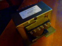
I have C-core trafos/1.5A and switch diodes
1.5A trafo should be sufficient, right
Im a bit concerned about grounding
And resistor values
As always, google google
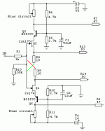
This popped up, and might be useful
FET Preamplifier
Also this Riedon company, but different matter
http://www.riedon.com/us - Home
Im planning to try seperate supply to cascode/Jfet
Cascode/Jfet on 35V rails
Output stage on 30V rails
I have C-core trafos/1.5A and switch diodes
1.5A trafo should be sufficient, right
Im a bit concerned about grounding
And resistor values
As always, google google
This popped up, and might be useful
FET Preamplifier
Also this Riedon company, but different matter
http://www.riedon.com/us - Home
Attachments
Last edited:
http://www.borbelyaudio.com/adobe/ae699bor.pdf
Fig.17, Q3, Q4.
The devices he uses will NOT do. Idss too low, giving only 2V Vds on the K170/J74.
Patrick
Patrick, thanks for posting this great link to Borbely's article. It is very good one and I think many people would appreciate reading it completely. I compiled both parts together for anyone interested in saving it. Here it is:
Attachments
On low battery😛
....
I have C-core trafos/1.5A and switch diodes
1.5A trafo should be sufficient, right
.........
hardly - for an amp with same current consumption .
I'm usually using 1.5A xformers for my preamps

or I didn't understood you correctly .......
just in case (just one of pretty often forgotten breadcrumbs) :
Attachments
I'm usually using 1.5A xformers for my preamps
or I didn't understood you correctly .......
Oh, small trafo fore input/driver only
Output stage will use trafo with 18-22V/18A, or so
If possible, the point should be better drive from cascoded/Jfet through raised voltage(35Vdc), and retain lower voltage(25-30Vdc) on output stage
Last edited:
- Home
- Amplifiers
- Pass Labs
- F5 power amplifier