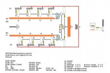
These fuses will be for + and - rails for both channels after capacitors (maybe i should have used fuse holders for PCB, but anyway now its too late for that solution). For primary i will use fast blow fuse (not decide yet - chassis mount or panel/socket mount).
regards,
O.
regards,
O.
no, slow blow for primary, i.e. TxAThese fuses will be for + and - rails for both channels after capacitors.......... For primary i will use fast blow fuse (not decide yet - chassis mount or panel/socket mount).
Fast blow for each of the secondary fuses, i.e. FxA
There is nothing wrong with putting the PSU fuses at the PSU. Fuse upstream of the first risk area for abusing the PSU.
BTW,
the FxA fuses can be half the maximum RMS/peak current into your standard speaker load.
25W into 8ohm is equivalent to 1.6Aac and 2.5Apk. Fuse at F1A to F1.25A for 8ohm speakers.
For 4ohm speakers, double the fuses at F1.6A to F2.5A
Last edited:
Hi Andrew,
yap -I made a mistake, slow in primary and fast in secondaries.
thanks for the clarification
yap -I made a mistake, slow in primary and fast in secondaries.
thanks for the clarification
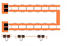
Hi,Andrew, do we fuse AFTER the caps because of inrush current?
if one fuses the secondaries before the smoothing caps without any slow charge circuit then the fuse value will need to be so large to avoid nuisance blowing that no effective safety advantage comes from fitting the fuses.
With +-30mF on +-25Vdc, I suspect that instead of F1A on 8ohm speakers one would need bigger than 3A to avoid occasional blowing, i.e. F4A or F5A
If not a dream, one open rail accidentally happened to me some time ago.
I would have thought this to result in a 25 volts ofset and all the bias current through the speaker.
But, surprisingly, no such an event happened.
I have already posted about this, but no answer.
Did i have a dream?
Or someone could explain this phenomena.
I would have thought this to result in a 25 volts ofset and all the bias current through the speaker.
But, surprisingly, no such an event happened.
I have already posted about this, but no answer.
Did i have a dream?
Or someone could explain this phenomena.
I would have thought this to result in a 25 volts ofset and all the bias current through the speaker.
But, surprisingly, no such an event happened.
If your experience is with F5, could your speakers have been saved by power limiter or thermistors ?
Ya.If your experience is with F5
If thermistor, it would be a magical one.
I do not use limiters. (would have to be magical too)
Last edited:
Michel le Bobo,
in case of the F5, at which side of the output devices is the bias referenced to ?
Secondly, what would the feedback do at the source of the JFETs if there was +/- 10Vdc at the output ?
(your BYW99 are heading for southern France first thing tomorrow morning)
in case of the F5, at which side of the output devices is the bias referenced to ?
Secondly, what would the feedback do at the source of the JFETs if there was +/- 10Vdc at the output ?
(your BYW99 are heading for southern France first thing tomorrow morning)
Hi Bobo,
In Chile everything is fine, Dollar is down so I can keep coming those big carton boxes full of the necessary to build the J2 and the Selectronic Triphon amplifier modules and compare them using the same supply which will use ECdesigns-s Charge Transfer supply and The Powerreg regulator from Teddy Pardo.
I plan to test Altmann-s SPLIF amplifier topology on the Triphon.
Appart that, we are preparing for presidential elections on December, which I hope will go without troubles...and the winter refuses to leave us...
Au revoir,
M
Michel le Bobo,
in case of the F5, at which side of the output devices is the bias referenced to ?
Secondly, what would the feedback do at the source of the JFETs if there was +/- 10Vdc at the output ?
I got it;
when one rail is open, the feedback resistor of the opposite half forces the corresponding Jfet to open , then there is no more bias on the facing mosfet.
Thanks Jacco, i missed this aspect.
Last edited:
No current from the open rail side is flowing through the load .
Neither any current from the opposite half (as stated upper)
So the load sees no current at all.
I do not really understand your question, Jacco.
Or am i wrong somewhere?
Neither any current from the opposite half (as stated upper)
So the load sees no current at all.
I do not really understand your question, Jacco.
Or am i wrong somewhere?
and the winter refuses to leave us...
Lucky people, here we are going into winter!

As stated manytimes upper:
Jfets prefer to be thermal coupled ( close to eachother)
It should be wise to count with cascoding in your lay out. Easy to strap if you do not use.
(10% mains variations could bring the rails to 33 volts which is the very limit.)
Jfets prefer to be thermal coupled ( close to eachother)
It should be wise to count with cascoding in your lay out. Easy to strap if you do not use.
(10% mains variations could bring the rails to 33 volts which is the very limit.)
- Home
- Amplifiers
- Pass Labs
- F5 power amplifier