I suppose your right
I will try
But I also intend to not be too hysteral about it
Meaning I wont let it lead to other compromises
Im still in doubt about the rail voltage
But I will probably stick to 25V with raised bias
Regarding Jfets
Are you sure that an effective heatsink on each Jfet wont be just as effective
And with each leg connected to solid wire
It should be able to deal with the worst temperature variations
I suppose the constant temperature variations is the problem
If temperature is more stable, DC variations should be less, even if both Jfet are not thermally connected
Just speculation
Anyway, it will be hardwired all through, and "layout" is just an overwiev, and things may change a bit once I start soldering
Attachments
Last edited:
Hi Uriah
Its the simple "paint", nothing special
But yeah, I like it
I think it followed with windows
At first it seems useless
But there are some useful tricks here and there
Let me know if you want to use it
I will tell you the tricks, wont take long
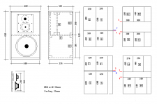
Also useful fore making speaker cutting plans
Just bought a used lazer printer cheap
Black and white, but ok fore simple schematics etc
Its the simple "paint", nothing special
But yeah, I like it
I think it followed with windows
At first it seems useless
But there are some useful tricks here and there
Let me know if you want to use it
I will tell you the tricks, wont take long
Also useful fore making speaker cutting plans
Just bought a used lazer printer cheap
Black and white, but ok fore simple schematics etc
Attachments
Last edited:
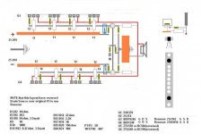
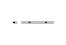
If of any interest, I have made a small change to supply
I was tempted to put in a couple resistors at the last supply cap, fore the Jfet/bias curcuit
But soon realised I better not do that, again
Instead I have "seperated" the last caps with a "thinner" wire
May not matter at all, or may be one of those little things that might make a small difference
btw, supply caps are planned to be BC 22.000uf/40V
Attachments
Last edited:
I suppose the constant temperature variations is the problem
Differences in Jfets temperature variations can lead to a no very stable offset.
Differences in Jfets temperature variations can lead to a no very stable offset.
Does Nelson physically clamp the Jfets together as I've seen some people do around here? Is that absolutely necessary? If they are physically close, but not touching/clamped will they still be stable?
Papa don't loose much sleep on that jfet kissing affair ;
at least looking on pictures of his Fugly! amps .
maybe explanation is that they're usually warm inside ....... Jacco will probably say - Papamps are cozy inside ........

at least looking on pictures of his Fugly! amps .
maybe explanation is that they're usually warm inside ....... Jacco will probably say - Papamps are cozy inside ........
That's what I thought at first, but after looking at the pictures again the transistors I could spot (which are not located next to each other) are the CCS transistors. I assume the Jfets are hiding back in the picture toward the rca jacks.
At any rate, if it's good enough for him, it's good enough for me. I have the Cviller boards so they are physically close together, but still separated by 1-2mm.
At any rate, if it's good enough for him, it's good enough for me. I have the Cviller boards so they are physically close together, but still separated by 1-2mm.
I do not know what Nelson does. This cannot be seen on Six moons review.
Both ways are working. In doubt, it cannot be wrong to make them touch when trying to do the best possible.
Both ways are working. In doubt, it cannot be wrong to make them touch when trying to do the best possible.
A blob of that arts/crafts glue stick stuff that you put in a gun and heat it up so that you can spread it ... if you seal them together with this they will stay the same temp as the glue will act as a heatsink and will heat up evenly. No.. it wont get warm enough to turn back into glue.
Ri
Ri
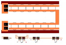
If the Jfets are glued into a massive chunk of aluminium, the temperature will just be below that of the inside box, 100% stable, always
I have considered this before, but thought it was much too impractical, in many ways
But the solution is quite simple
Place the Jfets horisontal
Then the massive heatsink can be screw mounted
Oh, yeah, drill a few exstra holes fore future mods, like a cascode
I have considered this before, but thought it was much too impractical, in many ways
But the solution is quite simple
Place the Jfets horisontal
Then the massive heatsink can be screw mounted
Oh, yeah, drill a few exstra holes fore future mods, like a cascode
Attachments
Last edited:
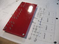
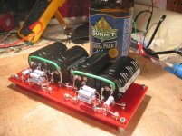
i made some progress tonight - doin' it the "big dumb way".. 33,000uF Panny UP x4. Panny power resistors. red G-10 board is 3-1/8 by 6-3/4. block rectifiers will flank the board, mounted directly on the chassis bottom.
Attachments

Last edited:
 , im still working with enclosure (sanding, dtilling ...boring) i hope amp will be ready till end of next week.
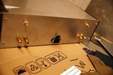
I had to limmit the bandwith because I got oschillation(uncuntrolled heating)when connected to a DAC via transformers.Anyway I used a 2,2nf across R10 and that stopped the oschillating(heating)but I think I got some less detals after,can the 2,2nf cause that?Should I use a smaller cap to keep out of the hearing area?I find that the most important details relate to the bandwidth.
The typical - 3dB point is out around 1 MHz, so without
compensation you can see all manner of effects.
Any time there is a question about this possibility, it's helpful
to throw a small capacitor across the feedback resistors and
see if it changes anything.
😎
I had to limmit the bandwith because I got oschillation(uncuntrolled heating)when connected to a DAC via transformers.Anyway I used a 2,2nf across R10 and that stopped the oschillating(heating)but I think I got some less detals after,can the 2,2nf cause that?Should I use a smaller cap to keep out of the hearing area?
Hi Ryssen,
I think R10 is a ground reference, not part of the feedback. To limit the bandwidth the cap needs to be on R5 and R6 (plus R7&R8 if used). Perhaps you can also consider increasing the gate resistors (R9, R13, R14) to see if it fixes the problem? Trimpot might be a friend here. If I'm mistaken (quite possible as my grasp is tenuous) someone please correct me.
Garrett
Correct, it is R6-8
I was recommended a cap in the pf range, but to be checked with instrument
I suppose that if you mount the wrong size cap you will just get a "ringing", and still have not dealt with the problem
Isnt 22-100pf often used
100pf is like 0.1nf, right
If you use multiple outputs, its also been adviced to increase R11/12 source resistors to maybe about 1ohm
Last edited:
In the manual it says"You can limit frekvency responce by an input capacistor across R10,and allso in the feedbackloop with capasistance across R5 and/or R8,i have choosen not to"
I tried caps across R5 and R8 with no effekt on the problem,cap across R10 had effekt,maybee to much...
I tried caps across R5 and R8 with no effekt on the problem,cap across R10 had effekt,maybee to much...
I tried caps across R5 and R8 with no effekt on the problem,cap across R10 had effekt,maybee to much...
Ofcourse, it makes perfect sense
R9 and R10 are there exactly to deal with problems like yours, oscillation caused by a connected source
- Home
- Amplifiers
- Pass Labs
- F5 power amplifier