It looks good so far.
I don't think I would go for 6 pairs.
I am not sure whether the input Jfets are capable of driving 6 pairs of output mosfets.
Nelson might be able to provide advice with this.
What I would do, is plan your lay out for 4 pairs, but instead of installing all 4 pairs, try 2 pairs first see how it sounds and then install 4 pairs and see how it sounds.
You could do one channel with 2 pairs and one channel with 4 pairs to hear the difference.
If you are looking at higher bias currents, then don't skimp on the transfomer VA rating. To be safe I would go for 500VA per channel, although 300VA per channel would be ok.
Last edited:
I was concerned about those issues
thanks
I think Nelson already gave his advice, to try cascoded
And raise impedance on source resistors
Why F5 when theres a Burning amp coming
I like the simplicity
But maybe we are pushing it too far
If it is say a 40watt biased to 20watt classA
Will it be free of crossover problems if used only to 20watt, or will there be crossover problems all the way, no matter how hard its driven
Last edited:
If you have 4 Ohm speakers.
I would aim for 3A per channel, provided you have enough heatsinking to dissipate the heat and a 500VA transformer per channel.
If you have 8 Ohm speakers, 2A should be plenty.
I would aim for 3A per channel, provided you have enough heatsinking to dissipate the heat and a 500VA transformer per channel.
If you have 8 Ohm speakers, 2A should be plenty.
If it is say a 40watt biased to 20watt classA
Will it be free of crossover problems if used only to 20watt, or will there be crossover problems all the way, no matter how hard its driven
No, it is directly related to how hard it is driven. I would not use less than 1.2A bias though.
Just wondering if I need a different resistor, R1 & R2
I also posted this on the Daniels F-5 group buy. There! I added the pics....
Thanks for any advice,
Russellc
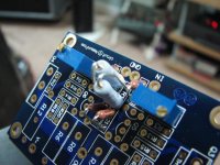
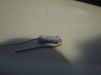
For R1 and R2 in my Tech-DIY F-5 kit I received the pictured resistors, 10 ohm 2 watt. The Daniels board has very small resistor locations, and has been discussed before, sometimes the resistors have to stand up. When it came to R1 and R2, there diameter would not allow them to stand side by side, so by offset mounting them, I can get them to fit. Question: I keep wondering if maybe
The caps were spec'd or selected wrong? I will also email Tech-DIY, but I figured this had come up before and is no biggie. I just didnt see the need for a 2 watt resistor in this location?
These arent soldered in place yet, so no big deal if anyone sees a problem, these solder pads are awful small for a tube guy, dont know how much of my resoldering they will tolerate!😱
I also posted this on the Daniels F-5 group buy. There! I added the pics....
Thanks for any advice,
Russellc
Attachments

Last edited:
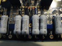
Are you sure they are 10ohm, and not mistakenly the R11 and R12
Yes. They are 10 ohm, 2 watt. Just double checked. The 10k ohm are R21 and R22 the two little brown Dales just behind the 10 ohm blue ones I'm asking about. R11 and R12 are .47 3 watt on my schematic? I was wondering if the 10 ohm should have been a smaller dale like the others... any other Tech-DIY kit users out there?
Russellc
Attachments
Last edited:
I would say that tinitus is partially right. The resistors R1 and R2 should be small 10 ohms not large blue 100 ohm. You should have four of those blue ones for R5, R6, R7 and R8.
I would say that tinitus is partially right. The resistors R1 and R2 should be small 10 ohms not large blue 100 ohm. You should have four of those blue ones for R5, R6, R7 and R8.
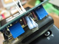
They are not large 100 ohm, they are large 10 ohm. The ohms are correct, I just thought it odd the rating was 2 watts. R5, R6,R7 and R8 are 100 ohm 3 watt.
So is this an inappropriate resistor mounted as I showed, requiring me to get the proper (smaller, the ohm value is correct) sized unit for best sound? Here are the 100 ohm R5-8:
Russellc
Attachments
Last edited:
You can use the 10 ohm 2W if you can squeeze them in there - I seriously doubt you'll be able to hear any difference.
The 10 ohm "big blues" are shown in the parts list on the Tech-DIY site as: "10R, ppc 10" whatever that means...
Russellc
Russellc
Well, if I may chime in -- the 10 ohms are now Panasonic 2W which are slightly larger than the Vishay PPC. You can sneak by with 1W here, but under some conditions 1W will fail. I used Dale 50R instead of the parallel 100R, but popular sentiment seemed to favor the former, so that's what is going out. The small wattage resistors are Mil-Spec RN55 or CMF.
I am disappointed that some folks didn't like the Ohmite 0.47 ohm TWW5 resistors -- these really get the heat off the board and are quite compact and low reactive impedance, and I used them as "one more worthy than I" had employed them in another amplifier article. In this application I have used Mills, Halco, Caddocks and the Ohmites. Horses for courses I guess.
The F5's I have in use have Caddocks in the 10R, 50R and 0.47R positions. These are attached to the heat sink as they won't dissipate much more than 1W on their own, but I burned my own PCBs for the application. I also pimped the input circuit a bit so that the two halves would behave a bit better at ham radio frequencies! This is ridiculous for audio...but my square wave has a faster rise time than your square wave!
If there was a figure of merit for elegance and simplicity vs sound quality, this amplifier would win hands down.
Question about the right value bias resistor
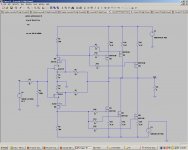
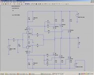
I did design the layout after these schematic , just finish it now .
These week I will each the PC board for the cascode version F5 .
I'm planing to use 36-37V rail power supp .
Also I would like to order the resistors from Parts connexion near future .
I have a important question : Which resistor set up the bias .
With 36V rail I would like to set up the bias between 2-2.4A .
Would you please let me know the resistor value for the right bias .
Thank you
Greets
HelloGo for it.
Bias around 1.7A to 2.4A, or higher if you have the necessary heatsinking.
I did design the layout after these schematic , just finish it now .
These week I will each the PC board for the cascode version F5 .
I'm planing to use 36-37V rail power supp .
Also I would like to order the resistors from Parts connexion near future .
I have a important question : Which resistor set up the bias .
With 36V rail I would like to set up the bias between 2-2.4A .
Would you please let me know the resistor value for the right bias .
Thank you
Greets
Attachments
Well, if I may chime in -- the 10 ohms are now Panasonic 2W which are slightly larger than the Vishay PPC. You can sneak by with 1W here, but under some conditions 1W will fail. I used Dale 50R instead of the parallel 100R, but popular sentiment seemed to favor the former, so that's what is going out. The small wattage resistors are Mil-Spec RN55 or CMF.
I am disappointed that some folks didn't like the Ohmite 0.47 ohm TWW5 resistors -- these really get the heat off the board and are quite compact and low reactive impedance, and I used them as "one more worthy than I" had employed them in another amplifier article. In this application I have used Mills, Halco, Caddocks and the Ohmites. Horses for courses I guess.
The F5's I have in use have Caddocks in the 10R, 50R and 0.47R positions. These are attached to the heat sink as they won't dissipate much more than 1W on their own, but I burned my own PCBs for the application. I also pimped the input circuit a bit so that the two halves would behave a bit better at ham radio frequencies! This is ridiculous for audio...but my square wave has a faster rise time than your square wave!
If there was a figure of merit for elegance and simplicity vs sound quality, this amplifier would win hands down.
So this is the correct part, then is my implimentation acceptable as shown in the pics, or does the Paul Daniels board need different resistors? They just looked a little awkward in there, but if this will present no problem, this is the way I will do it. Seems like most BOM I've seen just use 1/2 watt, one had .6 watt... I'd just like to assemble this board! I emailed you about a couple of missing pots in one of the kits, I'll see if I can call tomorrow.
So what say ye about the way I've mounted them?
Thanks
Russellc
Hello
I did design the layout after these schematic , just finish it now .
These week I will each the PC board for the cascode version F5 .
I'm planing to use 36-37V rail power supp .
Also I would like to order the resistors from Parts connexion near future .
I have a important question : Which resistor set up the bias .
With 36V rail I would like to set up the bias between 2-2.4A .
Would you please let me know the resistor value for the right bias .
Thank you
Greets
At positions R5 (500Ohm resistor) and R8 (400Ohm resitor) on the schematic you need a 5k multi turn trim pot in parrallel with a resistor somewhere between 700Ohm and 1k
Attachments
Last edited:
Hello
Thanks for the fast answer , I will have to modify my the layout .I made it after your schematic with out the 5K trim pots
Is not possible at first I set up the right bias with trim pot after I replace them with resistors ?
Greets
Thanks for the fast answer , I will have to modify my the layout .I made it after your schematic with out the 5K trim pots
Is not possible at first I set up the right bias with trim pot after I replace them with resistors ?
Greets
Possibly, but you are also adjusting the dc offset here as well. So it might be hard to get the exact values you need to get the dc offset and bias where you want them.
Having said that you might be lucky.
If you are going to use a trimpot first with out the resistor in parrallel. Then you need a 1k multi turn trimpot not 5k.
Having said that you might be lucky.
If you are going to use a trimpot first with out the resistor in parrallel. Then you need a 1k multi turn trimpot not 5k.
Thank you very much
I will make place for the trimpot to and when I set up the bias and the offset if I can buy the right value resistors I will replace them .
If not I take your advise trimpot & resistor parallel!
Thank one more time .
Greets
I will make place for the trimpot to and when I set up the bias and the offset if I can buy the right value resistors I will replace them .
If not I take your advise trimpot & resistor parallel!
Thank one more time .
Greets
I will be very interested to hear what you think once it is finished.
I am confident this will be a very special amp.
Don't skimp on the transformers or heatsinking. Aim to dissipate 200W per channel. Something like Conrad heatsink MF35-151.5 (2 per channel),total of four for stereo.
500VA to 800VA transformer per channel.
I am confident this will be a very special amp.
Don't skimp on the transformers or heatsinking. Aim to dissipate 200W per channel. Something like Conrad heatsink MF35-151.5 (2 per channel),total of four for stereo.
500VA to 800VA transformer per channel.
I have very large heat sink , the enclosure was design for Aleph2 , it is about 35-40lb just the heatsink .
I didn't finished the A2 yet . First I will finish and test that . If I like the sound I keep it . But also I want to test these cascode verizon to . I'd like your test result!!
For cascode I use 2SK1058 & 2SJ162 orig Hitachi .
I have a toroidal transformer from Plitron 30-0-30VAC 1KVA . I think That will be OK for the two channel.
I plan to use 3 pair power mosfet per channel .
I have at home matched IRF240 , I will have to buy IRF9240 or something equivalent from another company . I read the IRF9240 not the best choice .
Thank one more time .
Greets
- Home
- Amplifiers
- Pass Labs
- F5 power amplifier