Nelson always advocates high Vds, so I leave you to decide for yourself.
😉
Patrick
PS I checked those graphs for 2SK1530 and they are essentially the same. They are also closer to each other between N & P than some other MOSFET pairings.
.
😉
Patrick
PS I checked those graphs for 2SK1530 and they are essentially the same. They are also closer to each other between N & P than some other MOSFET pairings.
.
Last edited:
as Patrick wrote , and I think it's already spoken previously - if you use Toshibas for output - you really can go as low as +/-12V without significant sacrifice in any area of operation .
btw - regarding that solution I mention the other day - now I spotted Juma's "F5 meets Buzquito" thread ;
that's what I meant ...... just to clarify - not to urge you in that solution .
btw - regarding that solution I mention the other day - now I spotted Juma's "F5 meets Buzquito" thread ;
that's what I meant ...... just to clarify - not to urge you in that solution .
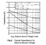
Well, that's kinda where I'm coming from also. At one watt the Cs are resonable but getting closer to the rail the C numbers start getting serious. Comparing IR devices to Toshiba's do you think the C curves are much different? The Tosh parts obviously have some different internal sructure going on.
I've just got one more thing to say. for the last 3 years I have been doing some MOSFET testing that ends up on datasheets or verifies the data already on them, for one of the mfgs where talking about. At least once a week my manager says "data sheets lie!".
For the sake of completeness, C vs Vds for IRFP9240.
.
.
Attachments
Last edited:
There is no reason for them to publish wrong curves.
The lie is sometimes in under what conditions figures (like Yfs or Ciss) are specified.
Patrick
The lie is sometimes in under what conditions figures (like Yfs or Ciss) are specified.
Patrick
Using my eyes, as a percentage change, say from 20-10Vds they look very similar. And not as rediculous as is sometime depicted.
So, a 16V rail, as you have chosen, does seem quite viable.
So, a 16V rail, as you have chosen, does seem quite viable.
There is no reason for them to publish wrong curves.
The lie is sometimes in under what conditions figures (like Yfs or Ciss) are specified.
Patrick
This is true. We certainly are not intentenally doing such things. Some of it also has to do with production/process variance etc. Personally I get a kick out of the Vgsth 2-5V? Give me a brake. But, it is not exactly a targeted parameter in the process. I have not seen such a wide spread in the products or parameters I've worked with.
as Patrick wrote , and I think it's already spoken previously - if you use Toshibas for output - you really can go as low as +/-12V without significant sacrifice in any area of operation .
btw - regarding that solution I mention the other day - now I spotted Juma's "F5 meets Buzquito" thread ;
that's what I meant ...... just to clarify - not to urge you in that solution .
ARG, I just took out of some UPSs four gigantic transformers that, with 100V input, gives 11.3VAC out. Toshiba MOSFET are available in the grocery store here. I think I will give it a try next week.
D.
LOL 😀... Toshiba MOSFET are available in the grocery store here...
When I first moved to Phx AZ 35 years ago, we had a Grocery store where aside from groceries, you could get a pair of Jeans, a pair of tennis shoes, a Pizza, breakfast, lunch or dinner, a six pack, a 357 magnum, the rounds to shoot in it, a lawn mower, a TV, movies etc. The original "Super Store". MOSFETs? Now I've heard everything 😀
the decision is easy.I still did not understand where I should stand.........................
...........But I am not sure if for me it's better to go with a parallel mosfet or the balanced.
For high impedance load (=low current demand) go bridged/balanced.
For low impedance load (=high current demand) go parallel.
ARG, I just took out of some UPSs four gigantic transformers that, with 100V input, gives 11.3VAC out. Toshiba MOSFET are available in the grocery store here. I think I will give it a try next week.
D.
you can always shoot me with dozen of them

just try , they're killer for any Mini Papamp
Yes, AndrewT, that is kinda what I was getting to in a long post a few pages ago. And, ZMs recomendation also. And as he said, it's not really a good idea to expect to get both in the same circuit.
Having said that, we have been focusing mostly on ClassA and this amp can do a pretty good job with the AB operation for higher level transients. It should be possible to set an operating point in there somewhere and take advantage of the balanced circuit without suffering to much of the didadvantages.
Having said that, we have been focusing mostly on ClassA and this amp can do a pretty good job with the AB operation for higher level transients. It should be possible to set an operating point in there somewhere and take advantage of the balanced circuit without suffering to much of the didadvantages.
think of the way "they" do it with chipamps. There they are crippled with current limiting and must do something to allow chipamps to drive high current loads.
Paralleling gives the pa100,
bridging gives the ba100.
both gives the bpa200 and bpa300. Here the extra drive for the higher impedance comes from the bridging and the extra current demand from the low impedance is met by the paralleling.
The F5 can be assessed in a similar manner.
One F5 to one driver is great.
One F5 to a high current driver takes the F5 into ClassAB.
Parallel the output devices for increased output current, but that increased current will be in ClassAB unless one also increases the bias current. ( I am still talking unbalanced).
If one wants increased ClassA current then the bias must be increeased. (here I see the important distinction between bias of an output stage and total quiescent current drawn from a common PSU).
A dual output F5 with both of the upper devices and both of the lower devices biased to 1.3A for a total bias of 2.6A will allow ClassA current to 5.2Apk.
Now bridge or balance that dual F5 into a Dual F5x and you have created a BPA type of topology.
The bias through each output device is 1.3A.
The total bias of one half of the bridged pair is 2.6A and the total quiescent current drawn from the PSU is just slightly over 5.2A (about 16mA over).
A 4r0 load can now be driven to I^2 * R power = 5.2^2 * 4 / 2 = 54W using 8output devices and lots of heatsink.
It is cheaper and more efficient to use 4devices in a PA version running from higher supply rails to get that 54W of ClassA into 4r0 but without the performance benefit that balanced gives.
You will change the sound by paralleling output devices as you changed the total capacitances that the input stage has to drive, and hence the open loop frequency response. Yes, you will get some of it back in close loop as your open loop gain also increases. But this is like opamps which has the first open loop corner frequency at well below 1kHz. i.e. the circuit has to work increasingly harder with frequency above 1kHz.
While the F5 is not my design, I try to layout closed loop circuits such that the first open loop corner frequency is above 20kHz. That way I can get away with low loop NFB (<=30dB).
Patrick
While the F5 is not my design, I try to layout closed loop circuits such that the first open loop corner frequency is above 20kHz. That way I can get away with low loop NFB (<=30dB).
Patrick
- Status
- Not open for further replies.
- Home
- Amplifiers
- Pass Labs
- F5 For Low Z Loads ?