
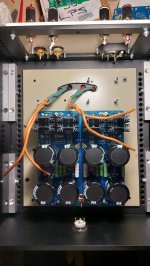
Boards will be mounted on stands and bellow will be an iron subchasis that will screen the transformer from the circuitry, in the box.... box is right now, upside down..
.
.

Yes, PS Ground to NTC to chassis.
Yes, PS Ground to L/R amplifier board Ground.
For me, no to PS Ground to speaker Ground. The reason is that speaker Ground, input Ground, and amplifier circuit Ground should all be at the same Ground potential. Because the PS Ground is connected to amplifier circuit ground by a wire, and wire has resistance, that puts the amplifier circuit Ground at a different Ground potential than the PS board Ground. So if the speaker ground attached directly to the PS board is at one potential and the PS ground and input Ground on the amplifier board is at a different potential, that can be a ground loop issue.
I connect the input Ground and speaker Ground to the amplifier board.
I also twist the input+ and input Ground wires together from RCA to amplifier board. I twist the speaker+ and speaker Ground together from amplifier board to speaker out connectors. I twist the V+ V- Ground from PS board to amplifier boards. This is to minimize loop area and minimize the wires acting as antennas, all to minimize noise.
I do this with all of my amplifiers and they are noise free with my 103dB speakers. It does help that I use CLC filters instead of CRC though.
Some info on twisting wires:
Twisted wires
Twisted wires 2
Got it.....
I also intended to do like that but was asking to be sure.....
One more question - can i connect the NTC to chassis at those 2 connectionpoints with 3 screw terminals where i have also ground or should i also connect that like in my sketch in my previous post....
(What i draw, i don't particularly like - it is not clean looking but right now i can't choose what i like as i need to make it work noise free)
What i will also do is a mod suggested in post #67 of this thread....
Hope this with new psu board will do the trick....
Cheers
Hope this with new psu board will do the trick....
Cheers
Yes you can connect the NTC to the screw terminal.
And the HBR should help.
And the HBR should help.
Problem is, if i do that, then i am in fact connecting everything almost to a one point which is not right.....
Ntc is not a problem imho, but amplifier grounding/ signal grounding.....
Ohh well.... will do it that way and see... hope that mod with signal ground lifting will help...
Will all let you know
Ntc is not a problem imho, but amplifier grounding/ signal grounding.....
Ohh well.... will do it that way and see... hope that mod with signal ground lifting will help...
Will all let you know
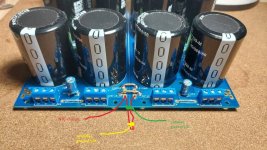
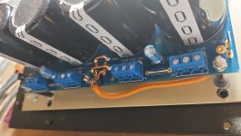
I am refering to a schematic in post #53... there you need to select where to connect what to the ground... here on this universal psu board you have two ground planes connected in one point as a star ground, but what i am missing is connection points where i deliver the ground to amplifier board... so using this i will probably use screw terminals to connect those to the ground on the psu board like everybody did so far...
You have a point. This board is a bit too universal. But yes, connect amp boards to screw terminals as far away from the high current junction between the two halves. Ime the quietest approach is to choose one of the sides, and connect all audio gnds to one block. But you can try different ways and choose the best.
.... then I replaced the "thin" ground wire with a shorter, thicker (black) one, and got rid of NTC:
Yes my friend... thank you for sharing those pics... i had something like that on my mind too..
...
I can also make something similar to that.... a little loop from one ground to another and connect everything on that loop like in post #53 without using speaker returns... those should he better connected on the amolifier board as i have been told... problem is, if i do that, i will alsways have some current flowing from amplifier boards towards psu board... and if i do exactly like in post #53 then i will only share a gnd potential to amplifier boards without a current.....
I will probably try the easiest thing to connect everything and go from there...... if it works, great, if not, then i will think from there.....
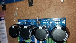
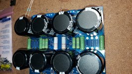
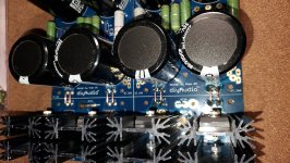
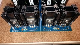
O.k.... this is every segment of that power supply board...
Just to have it there.....
On the output i made a loop - there i will connect the chassis through CL60
Just to have it there.....
On the output i made a loop - there i will connect the chassis through CL60
Attachments
Tomorrow i need to cut those traces on my amplifier pcb and instal 3R9 HBR resistor to lift the signal ground
- Home
- Amplifiers
- Pass Labs
- F5 buzzing issue