Ben, hmmm... now when i think of it - you are making a very good point there - i haven't thought about it correctly....
i can lift the legs of R2, R3 and R4 and connect those in the air with HBR that will go to power supply ground and on that connection point where HBR, R2, R3 and R4 meet together i can connect signal ground....
i can lift the legs of R2, R3 and R4 and connect those in the air with HBR that will go to power supply ground and on that connection point where HBR, R2, R3 and R4 meet together i can connect signal ground....
i am looking at pcbs... it seems to me that there is a single line connecting INgnd and GND... just in between them... maybe i just need to cut that line and put the resistor in between INgnd and GND and that will be it....
correct me if i am wrong but it seems that this would be the best to do....
correct me if i am wrong but it seems that this would be the best to do....
Attachments
I had another hard look at the picture of the pcb and I now see the connection of R2 to Ground. The easiest way to connect the HBR is to lift the ground end of R2 and connect there.
Also note that I edited my previous post to show the HBR connected to R2 only. I don't think the other ground needs to be lifted. At least try only R2 lifted and see if that works.
Also note that I edited my previous post to show the HBR connected to R2 only. I don't think the other ground needs to be lifted. At least try only R2 lifted and see if that works.
Attachments

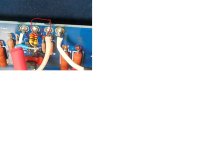
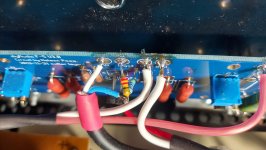
Alternatively, you could lift the ground end of R2, disconnect the INgnd wire from the INgnd pad on the board, solder the INground wire to the lifted ground end of R2, solder one end of the HBR to the ground end of R2 and solder the other end of the HBR to INgnd pad on the board. Then no cutting is needed.
that is exactly what i did .... pic's included.... it is buzzing a bit more then it did before - and it added some lower end to the buzzing (maybe some hum)...Alternatively, you could lift the ground end of R2, disconnect the INgnd wire from the INgnd pad on the board, solder the INground wire to the lifted ground end of R2, solder one end of the HBR to the ground end of R2 and solder the other end of the HBR to INgnd pad on the board. Then no cutting is needed.
HBR is 22R and when i was removing R2 i broke one of them (room is tight there), so i had to replace both of them with some Vishay metal-film...
point is - it is stil buzzing and now a little bit more then before.... arrrghghghh 👽👽😱
Attachments
I am at a loss too.
The best thing to do is to approach it methodically. With the HBRs in place go back to the Hifisonix debugging routine:
1. Power up with no inputs, does it buzz?
2. Connect the left input to the right input with a RCA cable. Does it hum or buzz?
3. Unplug your source component from the AC power. Connect one channel to the amplifier. Any noise? Connect the second channel. Any noise?
4. Plug the source component into the same AC outlet as the amplifier and power up the source. Any noise?
i powered it up with inputs open - it is buzzing a little bit....
when i ground the inputs buzzing stops - dead quiet...
when i connect one channel to the source - it is buzzing like with the other connected....
when i ground the inputs buzzing stops - dead quiet...
when i connect one channel to the source - it is buzzing like with the other connected....
1, It buzzed with inputs open. That is a sign of wiring and/or layout issue. One item that is unknown to me is the power supply filter construction. It is your DIY component but I have not seen the underside of it and its wiring and layout. Also changing it from CRC to C would have added noise to the DC power. Views of the underside of the PS board are needed.
2. Did you connect the left input to the right input and listen for noise?
3. Connect one channel to source and it buzzed. Was that with the source component unplugged from AC?
The amplifier buzzing with inputs open is an issue that needs to be addressed.
2. Did you connect the left input to the right input and listen for noise?
3. Connect one channel to source and it buzzed. Was that with the source component unplugged from AC?
The amplifier buzzing with inputs open is an issue that needs to be addressed.
Ben - regards... thank you for sticking with me....
....
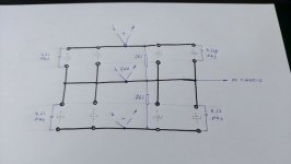
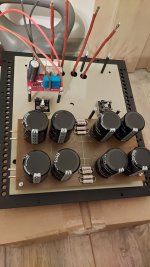
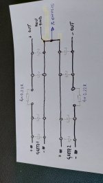
1. i can't take a picture of that part - it is hard to get under.. the only picture i have is from my conversation with a friend - it is eddited but with a sketch i will also send bellow, i think you will know how it is looking down under.... basically, where i had resistors at first, i removed then and formed a central point to take everything and move further from the board.....
before i had CRC and a sort of C shaped ground line, wanted now to try with that different ground look ... also removed R in series in that CRC to try to simplify things and make it more simetrical.
2. i did not connect left to right - both channels were the same type of buzz and i did not think it was needed to check in reverse
3. yes - source was disconnected and unplugged
....
seriuosly, right now i am close to give up ... no matter what i tried it did not work properly....
and now, with so many soldering, boards are looking like they went through a war, i am affraid of parts that might start falling appart because of so much soldering, heating up and cooling down (those psu wires and thick and you need to add extra heat to solder properly)... i don't know....it sounds more clear and tighter then my amp i am currently using but buzzing like this, i can't use it....
turning crazy ..
i don't know what to do to be honnest..... to proceed or just to give up.... it is now months i have been focused on it - other things are waiting and it became stress rather then joy... and that is never good.....
....
1. i can't take a picture of that part - it is hard to get under.. the only picture i have is from my conversation with a friend - it is eddited but with a sketch i will also send bellow, i think you will know how it is looking down under.... basically, where i had resistors at first, i removed then and formed a central point to take everything and move further from the board.....
before i had CRC and a sort of C shaped ground line, wanted now to try with that different ground look ... also removed R in series in that CRC to try to simplify things and make it more simetrical.
2. i did not connect left to right - both channels were the same type of buzz and i did not think it was needed to check in reverse
3. yes - source was disconnected and unplugged
....
seriuosly, right now i am close to give up ... no matter what i tried it did not work properly....
and now, with so many soldering, boards are looking like they went through a war, i am affraid of parts that might start falling appart because of so much soldering, heating up and cooling down (those psu wires and thick and you need to add extra heat to solder properly)... i don't know....it sounds more clear and tighter then my amp i am currently using but buzzing like this, i can't use it....
turning crazy ..
i don't know what to do to be honnest..... to proceed or just to give up.... it is now months i have been focused on it - other things are waiting and it became stress rather then joy... and that is never good.....
Attachments
The challenge with class A amps is that they are at full power all the time which demands a very good PSU with low ripple.
I think you need to find out if the hum is caused by PSU ripple or it is magnetic coupled noise. It seems the amp hums all by itself without being connected to any source. I have found that just CRC filtering is not sufficient to get a "hum-free" amp. Toriods with magnetic shield is also a good thing. A smps in an external chassis with additional filtering in amp chassis works for me. Push-Pull amps should have very good PSU ripple cancellation and other seems to have built a "hum-free" F5 just using CRC filtering. Maybe other F5-builders could give some advices or show how they built their amps. They you maybe could copy this and start all over 🙂
I think you need to find out if the hum is caused by PSU ripple or it is magnetic coupled noise. It seems the amp hums all by itself without being connected to any source. I have found that just CRC filtering is not sufficient to get a "hum-free" amp. Toriods with magnetic shield is also a good thing. A smps in an external chassis with additional filtering in amp chassis works for me. Push-Pull amps should have very good PSU ripple cancellation and other seems to have built a "hum-free" F5 just using CRC filtering. Maybe other F5-builders could give some advices or show how they built their amps. They you maybe could copy this and start all over 🙂
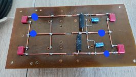
Looking at your picture and sketch, the layout probably contributed to the noise that you heard.
First I recommend re-installing the resistors to make the PS filter CRC. That will reduce the power supply ripple. With 108dB speaker, you need a low ripple power supply.
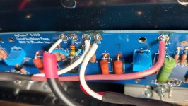
Second I recommend re-wiring the PS board to reduce the loop area. With 108dB speaker everything matters. Also the high ripple DC V+ V- Gnd from the bridge rectifiers should enter the PS filter at one end and the low ripple DC V+ V- Gnd should exit from the PS filter at the opposite end.
Please see the picture that I have marked up. The red, blue, and black lines are the V+ V- Gnd lines. The V+ and V- lines should be kept as close as possible to the Gnd line to minimize loop areas.
First I recommend re-installing the resistors to make the PS filter CRC. That will reduce the power supply ripple. With 108dB speaker, you need a low ripple power supply.
Second I recommend re-wiring the PS board to reduce the loop area. With 108dB speaker everything matters. Also the high ripple DC V+ V- Gnd from the bridge rectifiers should enter the PS filter at one end and the low ripple DC V+ V- Gnd should exit from the PS filter at the opposite end.
Please see the picture that I have marked up. The red, blue, and black lines are the V+ V- Gnd lines. The V+ and V- lines should be kept as close as possible to the Gnd line to minimize loop areas.
Attachments

@sparkle
I do not understand why are you using that PS board. To save money?
If the answer is: "to learn new things and try the real DIY nitty-gritty"... you should learn first about proper grounding, return currents segregation, RF noise, and coupling the noise to the ground.
Anyway, my intention is not to discourage you... here's the proper grounding. Enjoy...

Thank you for your answer.... the amplifier did not hum at all - dead quiet before i added HDR resistor and when i ground the input, it is dead quiet... it is not the ripple in the psu imho..... i had CRC before and different layout of psu - it was buzzing the sameThe challenge with class A amps is that they are at full power all the time which demands a very good PSU with low ripple.
I think you need to find out if the hum is caused by PSU ripple or it is magnetic coupled noise. It seems the amp hums all by itself without being connected to any source. I have found that just CRC filtering is not sufficient to get a "hum-free" amp. Toriods with magnetic shield is also a good thing. A smps in an external chassis with additional filtering in amp chassis works for me. Push-Pull amps should have very good PSU ripple cancellation and other seems to have built a "hum-free" F5 just using CRC filtering. Maybe other F5-builders could give some advices or show how they built their amps. They you maybe could copy this and start all over 🙂
transformer has an iron plate between itself and circuitry that is grounded... also i tried to cover it with iron box... nothing affected the amount of buzzing - the only time i got more buzzing is now when i pulled the signal ground away from psu ground by adding HDR resistor - now i have more buzzing and a bit of humming i guess too.......
that is exactly how i did it first time but then the ground was closer and in a C shape... i have uploaded first version that i rewired now with a sketch how i wired everything... it was buzzing the same... only time i had more buzzin with some humming is now when i added that HDR....Second I recommend re-wiring the PS board to reduce the loop area. With 108dB speaker everything matters. Also the high ripple DC V+ V- Gnd from the bridge rectifiers should enter the PS filter at one end and the low ripple DC V+ V- Gnd should exit from the PS filter at the opposite end.
Attachments
@Extreme_Boky - dear Sir - thank You for your kind answer - very nice of you for supplying the schematic..
i used that board because at first i did not know what caps i will get... so i bought only amplifier boards... that is bakelite - should be perfectly o.k. for holding the caps on something...
..
i don't pretend to know everything but i am not a complete begginer either ... problem is, i tried all the conventional ways i could think of to make it run but can't get rid of the buzz... that is why i am starting here as a complete begginer from ground up - since it does not run as it should, i can't say i was smart enough and every good answer is very welcome.
i already made what you suggested in your schematic and it was buzzing.... i tried not to use NTC, i did use NTC.. i even removed the connection of psu to chasis but left it connected to earth for security reasons....nothing worked there... always the same.... i even connected first time my loudspeaker gnd to psu like you have noted, not on the board... it did not made amp quiet. only when i disconnect interconnect from one channel at input it is completely quiet (or if i ground both channels, or disconnect both channels - the minute i make that loop with two input channels connected, it is buzzing)...
Last edited:
@Extreme_Boky - i checked the schematic again you were kind to provide.... i didn't make it completely the same - i could try to isolate more those three points one from another... seems i will have to rewire again everything.... hope my cap's will hold.....
once again - thank you so much...... will keep posted.....
once again - thank you so much...... will keep posted.....
I suspect the power supply or it's wiring, which is an un known. Odd it is quiet with inputs grounded, usually indicates something up stream of amp
My F5 build had a similar story at one point. Inputs shorted, dead quiet. Most setups, dead quiet....but, when I added a Roku box to system so I could pump Amazon prime music and movies in, I ran into problems. Needed a monitor to "see" Amazon, and when I did, it hummed like you talk of.
Never did resolve it back then, but finally did. It was true dual mono, all the way to the two power cords. I ran that p for years with no CL 60 "inrush" limiter circuit, just slammed it on. Finally got around to installing CL 60 arraignment. The two power cords came in the chassis through neutrik power cons. While disassembling them, I noticed I had reversed one of the ground positions and a power connection!
Problem solved. My point here is two sets of eyes are best, and right now there are no eyes on back side of power supply.
This amp WILL be worth the effort. Even if you need new boards and parts. The schooling alone is worth it. Plus, you will have working amp.
If you are ready to give up, I would strip everything out of amp, including the "slow start" and DC protection, at least for now. Papas amps are 3-4K, use the CL60 set up and no dc protection. Get it working in KNOWN format, then add those bobbles if you must. I don't.
Take clear pics a long the way, post them here as you rebuild. You will find the boo boo. This is a very simple amp, which makes it super frustrating in these situations. It WILL be worth it.
Russellc
@Russellc - my friend - thank you for your answer....
i tried passive preamp and it was buzzing with F5... also, i have had several amplifiers in this chain to try out and none was buzzing except Gaincard (just a slight buzzing when you get close to my tweeter/mid driver - i suspect Gaincard filtration caps are small and that was the problem) ....others were completely quiet or just a bit of humming as a result of the filtration or amp concept. no problem there... i only have a problem with F5 in conditions as noted above in previous posts....
...
i took a few deep breaths and i will not give up on it... i was really not sure what to do with it few days ago... been working on it for months and i felt preety sad about everything...
anyway, after your message here and some time to think, this is what i will do....
will dismantle everything back down to the screw and will mount it back again but this time not in a chassis.
what i will do, i will put power supply and transformer away from the amplifier boards - just a bit further away... i understand it is not exactly by the book (when you want to have short wires) but at least i will remove the issue of power supply and transformers maybe affecting the amplifier boards somehow...
also i plan to get the original psu board - seems like my filtration caps will be just perfect for that board - this way i will reduce possible problems...... maybe also a new set of amplifier boards - will see....
if everything works nicely, i will put everything into the chassis again.... hope that will be good then........
- Home
- Amplifiers
- Pass Labs
- F5 buzzing issue