Right, seems the one on my hard drive is a bit older. Anyways - what are these diodes good for? I did some scoping on the outputs of my preamp checking the reproduction of square and sinus waves I fed in the input. When my balanced F4s are connected but switched off the signal at the preamp output is heavily disorted and I can actually hear the test signal in the speakers. Presumably because there is a path through the diodes to the speakers and capacitances etc. mess with the signal...
Sven
Edit: Thanks 6L6. What would be the consequences/risk in removing them?
Sven
Edit: Thanks 6L6. What would be the consequences/risk in removing them?
Can anybody help me figure out the following:
Due to my chassis (heatsink size) and no need to have 25W, can I use only two out of three Mosfet buffers. Is that going to give me 16W output? And what else needs to be changed in order to make it work this way? I will use a 200VA from Antek that hope will suffice.
Thanks for your help.
Best regards,
Radu
I would stick with 3 pairs, because you will have lower distortion. You can also lower bias to about 1A total, but it will also increase distortion. I would build it as it is in the schematics to retain amplifier´s performance.
Zen mod,
Do you mean it will have a little more distortion a but the same harmonic balance?
The problem now is that I already have a standard 4u chassis and a 200va toroidal.
Radu
Do you mean it will have a little more distortion a but the same harmonic balance?
The problem now is that I already have a standard 4u chassis and a 200va toroidal.
Radu
Does anybody know from experience,how many power Mosfet I have to buy to be able to get a matched pair. Mr.Nelson's paper on matching mosfets reports that one can get 12 pairs from a stack of 150 mosfets, which is at a rate of 6:1 in order to match Vgs at 0.1V.
Thanks,
Radu
Thanks,
Radu
Last edited:
Zen mod,
Do you mean it will have a little more distortion a but the same harmonic balance?
The problem now is that I already have a standard 4u chassis and a 200va toroidal.
Radu
let say it this way - I'm using one pair of mosfets in source follower stage , and that's my fave small Pa's amp : Papa’s Koan (M)2 , an amp for living room | Zen Mod Blog
Does anybody know from experience,how many power Mosfet I have to buy to be able to get a matched pair. Mr.Nelson's paper on matching mosfets reports that one can get 12 pairs from a stack of 150 mosfets, which is at a rate of 6:1 in order to match Vgs at 0.1V.
Thanks,
Radu
if you have intention to make just that one , you can buy matched mosfets from few guys around ;
if you intend building something more , I believe that from 20+20pcs you'll have plenty matched N and matched P groups
there is also simplest solution - use just one pair in output , then you don't need any matching ..... you can even use IRFP150N and cousin , which is practically two usual dies,paralleled, in one case
Thank you so much Zen mod. All the above are great news. I am mainly a tube guy and this my first real SS amp ( I built few low low power discrete and IC amp when I was a teenager).
I like the idea of hybrid... A perfect combination between SS and tubes could lead to great sound.
I like the idea of hybrid... A perfect combination between SS and tubes could lead to great sound.
I have had very good experiences with these:
Impasse: http://www.diyaudio.com/forums/pass-labs/136835-impasse-preamplifier.html
Curly-F4: http://www.diyaudio.com/forums/pass-labs/250205-curly-f4.html#post3797109
BA-3: http://www.diyaudio.com/forums/pass-labs/195303-burning-amp-ba-3-a.html
Impasse: http://www.diyaudio.com/forums/pass-labs/136835-impasse-preamplifier.html
Curly-F4: http://www.diyaudio.com/forums/pass-labs/250205-curly-f4.html#post3797109
BA-3: http://www.diyaudio.com/forums/pass-labs/195303-burning-amp-ba-3-a.html
Anyone have any suggestions for Preamps to use with the F4?
Does anybody know from experience,how many power Mosfet I have to buy to be able to get a matched pair. Mr.Nelson's paper on matching mosfets reports that one can get 12 pairs from a stack of 150 mosfets, which is at a rate of 6:1 in order to match Vgs at 0.1V.
I seem to recall that this was for 12 pair of identical values. There are very
few projects that require 12 Fets in parallel.
😎
I have had very good experiences with these:
Impasse: http://www.diyaudio.com/forums/pass-labs/136835-impasse-preamplifier.html
Curly-F4: http://www.diyaudio.com/forums/pass-labs/250205-curly-f4.html#post3797109
BA-3: http://www.diyaudio.com/forums/pass-labs/195303-burning-amp-ba-3-a.html
The Impasse and BA-3 look very interesting. I will look more into them. Thank you.
Anyone have any suggestions for Preamps to use with the F4?
Hadn't read this post, but just answered that in the F5 Turbo thread http://www.diyaudio.com/forums/pass-labs/207103-f5-turbo-builders-thread-355.html#post4038526 - BA3B, or BA3 if you want to use the F4's unbalanced, or one of my favourites is the Pumpkin.
Last edited:
The Impasse and BA-3 look very interesting. I will look more into them. Thank you.
A nice preamp. Very nice.
It was designed to drive two F4s as balanced monoblocks to full output, giving 100WPC into 8ohm.
😀 😀 😀
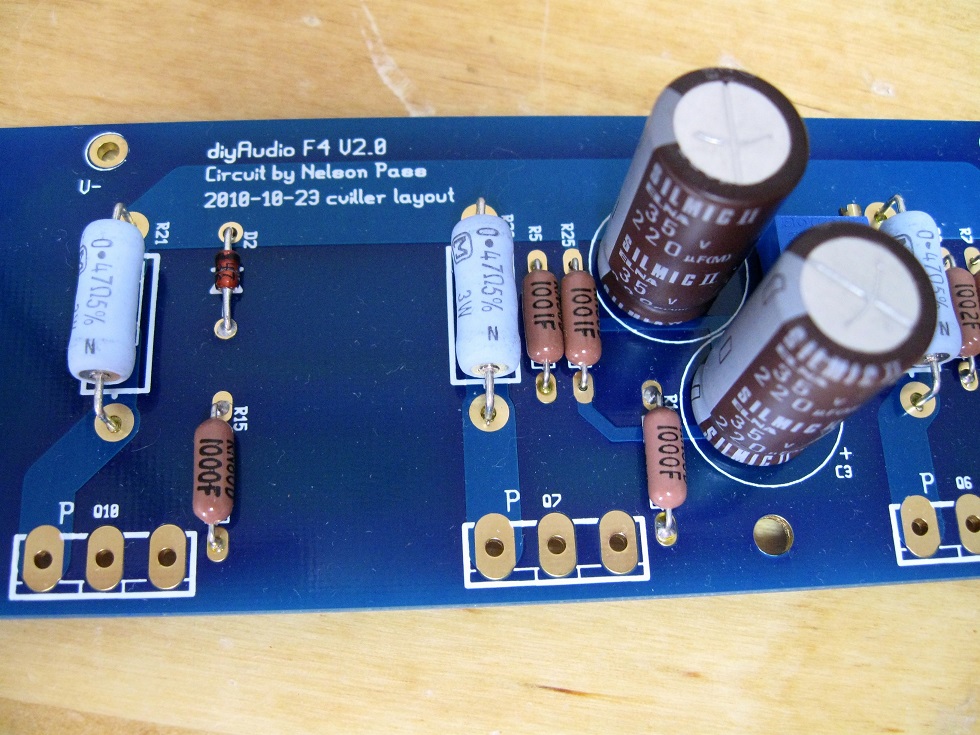
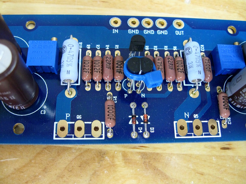
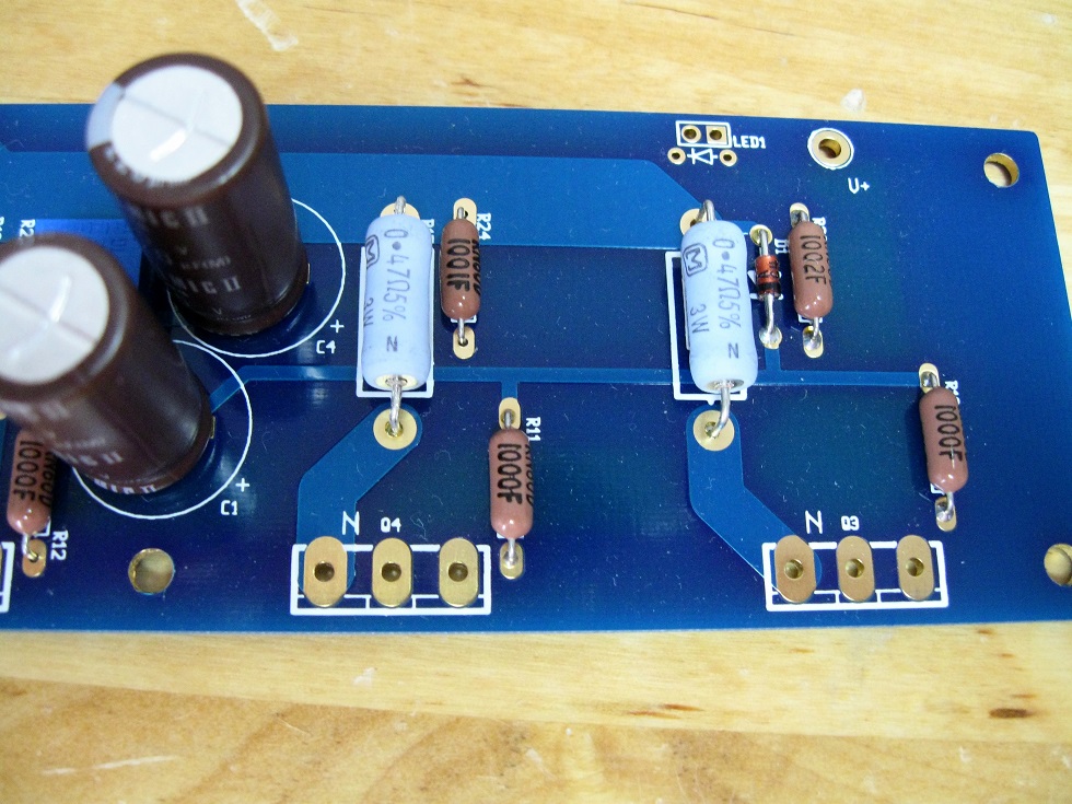
I completed my F4 and started one channel using a power supply that I had previously used, for a few months, to power my F5 built on Peter Daniel's boards.
I connected one multimeter across R21 and the highest bias I can get is 90mV. At that moment the multimeter connected across R16 measured 62mV and the DC offset at the speaker output was close to 1V.
I tried the second board and the results were similar. In both cases, with a speaker connected to the output, when touching the input with my finger I can hear a buzz. Whatever mistake I made, was apparently repeated on both boards and fortunately, not fatal.
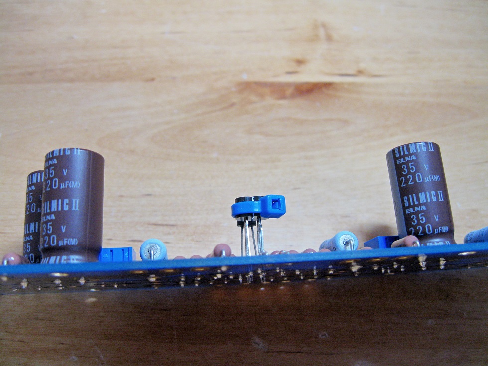
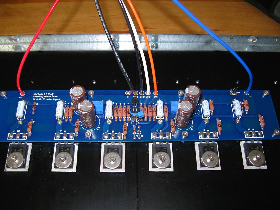
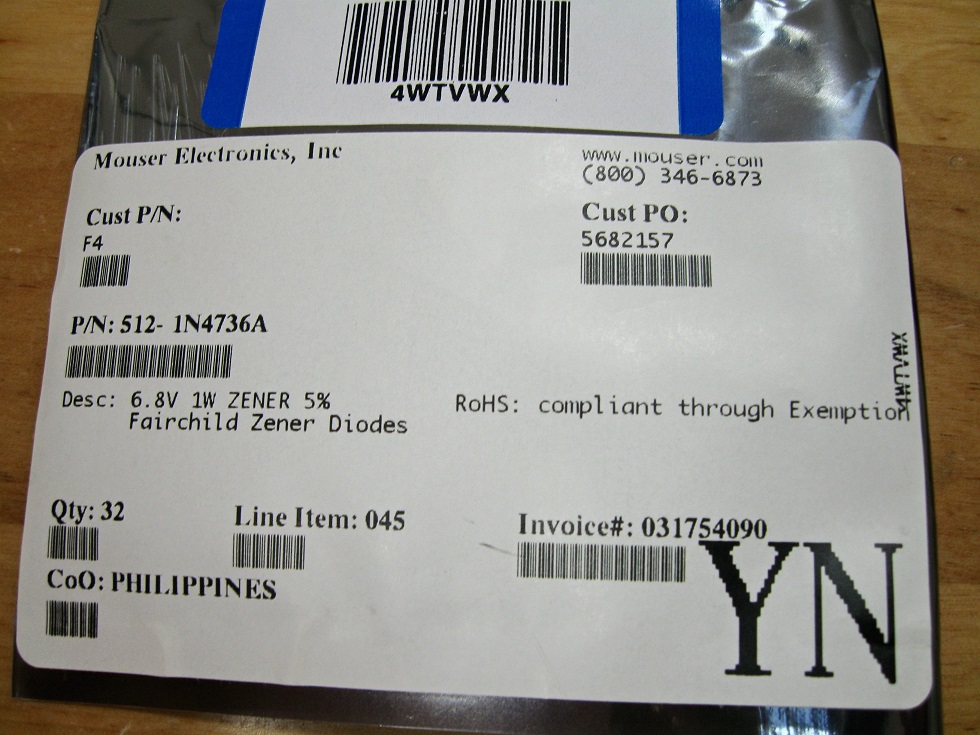
The component values were taken from the BOM downloaded from the DIYAudio store. The JFETs were purchased many years ago, while they were still in production. I selected devices which measured about 8.3 mA IDSS (using 5 1/2 digits multimeter). The MOSFETs are IRFP9240 (P-channel) and IRFP240 (N-channel) matched to within 2 mV. All components were tested before soldering them on the board. The Zeners (D1 & D2), which are hard to read on the pictures, were taken from the bag in the last one.
Any ideas of what could be wrong?
I connected one multimeter across R21 and the highest bias I can get is 90mV. At that moment the multimeter connected across R16 measured 62mV and the DC offset at the speaker output was close to 1V.
I tried the second board and the results were similar. In both cases, with a speaker connected to the output, when touching the input with my finger I can hear a buzz. Whatever mistake I made, was apparently repeated on both boards and fortunately, not fatal.
The component values were taken from the BOM downloaded from the DIYAudio store. The JFETs were purchased many years ago, while they were still in production. I selected devices which measured about 8.3 mA IDSS (using 5 1/2 digits multimeter). The MOSFETs are IRFP9240 (P-channel) and IRFP240 (N-channel) matched to within 2 mV. All components were tested before soldering them on the board. The Zeners (D1 & D2), which are hard to read on the pictures, were taken from the bag in the last one.
Any ideas of what could be wrong?
Attachments


I have 4 channels of F4 stuffed and biased. 4 channels of Ba3 stuffed and biased. Goal is a balanced (intergated) Bba3/F4. Currently I have a nice regulated supply for the Ba3 boards and two FW style power supplies for F4 (BF4). I have one 400VA 18volt toroid and one 300VA 18volt (in my F5). I am planning on getting a 600va for 4 F4 boards, put 400VA into F5, use 300VA currently in F5 to run 4 Ba3 channels. I guess the question is, is a 600VA 18v sufficient to power 4 F4 boards? One 300VA 18v adequate for 4 channels of Ba3? Sounds ok to me. I think the F5 will enjoy 400VA rather than 300VA currently in residence. Thanks! PS Ba3 boards biased to 1 volt, F4 boards biased to 200mv. I could leave the 300 in F5 and use 400 for Bba3.
Last edited:
.....
I connected one multimeter across R21 and the highest bias I can get is 90mV. ......
if you are sure that everything on pcb is by the book ............. then back it (with P1) to zero Iq , decrease R9 to 5K1 or 5K6 , then rebias
all that ref. to r0 6/4/07 sch from F4 SM/UM
Zen Mod,
While double-checking the values of the components against the BOM in the DIYAudio store, I noticed that some resistor values do not match the schematic in the F4 manual. R3 and R4 in the BOM are 22.1R and in the schematic 10R. R8 is 22.1K vs. 27.4K and R10, R11, R12, R13, R14, R15 100R vs. 150R in the schematic.
I usually bend the Vishay resistors' leads so the values remain visible after placing and soldering them to the PCB. When I posted the pictures I was hoping that some other member could spot something I may have missed. Can you see a mistake?
I don't mind attaching another resistor in parallel to R9 to lower its effective resistance, but I would like to understand what is causing the problem. Would you have a schematic with some expected voltages marked on it?
that's why I strongly despise public BOMs - every second guy is using wrong BOM 
and , that's why I'm always insisting on writing "ref. to ....", 'cause there is so many variations of projects that at least I am lost ........
point me to exact sch you're using (I'll ignore BOM) and I can comment is there anything wrong
edit - looking at sch (mentioned in my previous post) all differences are irrelevant ......... except R8 (upper TL431 resistor) - make it 27K , as Papa intended
Last edited:
- Home
- Amplifiers
- Pass Labs
- F4 power amplifier