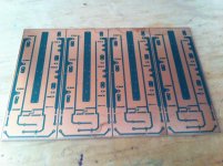
Buzz - how long are the boards, and can you daisy-chain them if you want more output devices?
I replaced the TL431, but it doesn't help.
Since then I tried a lot of stuffs, and finally be able to narrow down the problem, which is at C1. Here are the gist.
- The reason that the DC fluctuation at output symptom is voltage across TL431 isn't as still as it can be.
- When I soldered a 220µF electrolytic capacitor at C1, the problem appears.
- Replacing the 220µF electrolytic capacitor does not solve the problem.
- Soldering a 47µF film cap largely solved the problem, but soldering 220µF electrolytic capacitor on it brings the problem back.
- If I connect the 220µF electrolytic capacitor through wire with alligator clips, the problem disappears.
- If I clip the leads of the 220µF electrolytic capacitor directly without the wire, the problem came back.
So I thought, may be I need the resirtance of the wire. So I tried adding a resistor (1Ω, 5Ω and 22Ω). If I clip the resistor leads directly, the problem remains. If I connect the resistor through wire with alligator clips, the problem disappear.
Why is it that the wire with alligator clips seems to posses magical property? Any ideas? 😀
Btw, just for reference, I think I found the cause of the problem.
As mentioned I did everything that I can imagine around the TL431 with no luck. I got stuck and one thing lead to another, I neglected this project. Then one day I got an epiphany, and true enough the wildish voltage fluctuation went away when the 2SK170 is disconnected. So it's probably fried.
I've just buid F4. I have some questions:
1. Why C1 i C2 is so big?
2. Can I change JFet N+P Follower with only N+N-fet follower (re-design circuit)?
3. can i drive irfp power follower with BLS Pre, without j-fet follower (re-design circuit) ?
1. Why C1 i C2 is so big?
2. Can I change JFet N+P Follower with only N+N-fet follower (re-design circuit)?
3. can i drive irfp power follower with BLS Pre, without j-fet follower (re-design circuit) ?
Sorry. missed some questions. These boars are 6" long. THey will allow a bias at my chosen point of .5a/fet for total of 1.5a Iq. The SE bias will be about 1/10th of that. With a bridged amp , we are talking something like 30W class a into 8R, similar to the Firstwatt series. This is mainly a test of the Se bias concept as well as the FE boards that will be pushing it along. AB power will be higher due to available rail voltage. On my expected set of speakers, this will be an exuberant amount of power. That being said i may use more fets in the end.
PDYN -
1) So the AC component (the music signal) moving across the cap is very small, and the cap stays almost completely charged at all times.
2) Yes, you could, but as you say, it would be a re-design of the circuit and hold no resemblance to an F4 at all. Look at the Burning-amp 1 or BA-2 Single-ended output stage for ideas.
3) Yes, you can use the output from a Balanced linestage, and without the input buffer. The F4 was designed to be used as a bridge monoblock when driven through it's balanced input. It will give 100W into 8ohm this way.
You might as well keep the input buffer in the circuit, it's sonically invisible, and acts as a impedance matching circuit, letting the output stage operate optimally.
Which ones ? The f4 is a current buffer so the cap should have less effect because of no voltage gain . That is at least my take on it .So does this mean that there is no effect of the electrolytics on the sound?
I would listen first. If you like it, then you have the possibility of tweaking the sound with cap choice. If you don't like it, you saved that little bit'o money for the next build.
Last edited:
For C1 and C2.....I'll try it first with the standard 220u Elna silmic's and then maybe try 22u polyprops as they do show on sim to be sufficient. Maybe someone has tried that and can comment on it.
The values of the caps are so high to minimize the turn on plopp.....of course 22uF are enough for audio purposes but I suppose not to avoid the plopp.....🙂
The simulation can't hear the Plopp!
The simulation can't hear the Plopp!
Last edited:
You can try the solution Nelson used in BA-2
10uF of a good film cap or Elna 10uF/16V from the inputstage and 1000uF in the upper branch to avoid the Plopp!
10uF of a good film cap or Elna 10uF/16V from the inputstage and 1000uF in the upper branch to avoid the Plopp!
hi all
can sony 2sk82/2sj28 or semisouth r100 be adapted to work in this design
I,m looking for something they will drop into with minimal fuss and make 25 to 50w
Sheafer
can sony 2sk82/2sj28 or semisouth r100 be adapted to work in this design
I,m looking for something they will drop into with minimal fuss and make 25 to 50w
Sheafer
Last edited:
2sk82/2sj28 - yes ( more than few amps are floating around , made with them as follower stage)
SSR100 - you need counterpart for it ...... and there is none
SSR100 - you need counterpart for it ...... and there is none
hi Zen
that is what I was hoping to hear
any chance of one of your famous sketches ? I am thinking about one pair per channel
rgds Sheafer
that is what I was hoping to hear
any chance of one of your famous sketches ? I am thinking about one pair per channel
rgds Sheafer
frankly - in source follower iteration , I can't see any value of using old , made of preputium , parts ;
make F4 lookalike and save Sony parts for something where you can more exploit their rare transfer characteristic
say something as F6 complementary ....... there you can find one sketch of Mighty ZM, still untested
make F4 lookalike and save Sony parts for something where you can more exploit their rare transfer characteristic
say something as F6 complementary ....... there you can find one sketch of Mighty ZM, still untested
- Home
- Amplifiers
- Pass Labs
- F4 power amplifier