Finished my J2 variant 3 days ago. Now we're talking!! 😀...btw - J2 vs. BJ2 - they're not so different ...... any difference is strictly intentional - it's not fun making things exactly as Papa does
You know by now how satisfied I'm about this amp topology as we've a Serbian friend in common who called you this evening. 😉
With my precious DTQWT MKII loudspeakers by Troels Gravesen I'm in heaven! I can't imagine that a F4 can do it better than a J2 variant, oh, it should be your Babelfish J2 mighty Zen Mod! 😀 Or any SIT-amp from Papa... 😎
So, do a F4 have a chance against the J2 on efficient speakers? The low level detail from the Semisouth JFETs is beyond any FET-amp I've heard so far... Truly amazing and on par with the best SET tube amps I've heard but without their limitations...
Thanks to Papa for encouraging to DIY!! 😎
..........
You know by now how satisfied I'm about this amp topology as we've a Serbian friend in common who called you this evening. 😉.........
small world

......
So, do a F4 have a chance against the J2 on efficient speakers? ........
I think not

Good morning to all. Would it be plausible that a LU SRPp FE, biased slightly lower with higher rails, be able to match J2? EUVL found pretty nice sweet spot at lower levels. Drinving an crippled F4 of coure.
I think the F4 is a real truth-machine.
What it involves, going to come out of it.
But it requires a preamp, that I not have.
I wonder what Papa used for this?
What it involves, going to come out of it.
But it requires a preamp, that I not have.
I wonder what Papa used for this?
How exactly is it to build a crippled F4 with a BA3?
I thought of building them in modules and interconnect like a BA3 pre to a F4 power. The BA3 gain should be more than enough to drive a F4 properly from what i understand.
If someone could suggest a better way, I would be happy to learn it. 🙂
I thought of building them in modules and interconnect like a BA3 pre to a F4 power. The BA3 gain should be more than enough to drive a F4 properly from what i understand.
If someone could suggest a better way, I would be happy to learn it. 🙂
How exactly is it to build a crippled F4 with a BA3?
I thought of building them in modules and interconnect like a BA3 pre to a F4 power. The BA3 gain should be more than enough to drive a F4 properly from what i understand.
If someone could suggest a better way, I would be happy to learn it. 🙂
Crippled F4 is basically BA PP output stage. You make FE capable of driving it,like BA2 or 3, or even what FLG is suggesting. I thought an LU SRPP or mu Follower biased at about 300ma might do the job nicely.
Euh, any reference ?
I have been playin garound with the LU in sims for quite a while. After i get th eFairchild thing sorted, i plan to actually build it. From what i ahve read, th SRPP lperforms very well as voltage amplification stage into high impedance loads. Perhaps in this case, the F4 might be better suited than BA output. I hope to see.
no biasing network for the output stage....? 😕
I think tje 200R resistor should provide bias, but perhaps This is why FLG says it needs some work
indeed the current through the 200 Ohm seems to be sufficient to produce the necessary bias voltage....
I have not seen it in this way before....
elegant flg.....
I have not seen it in this way before....
elegant flg.....
the only point i just remember that the two 220uF also served as antiplopp when turning on...
but there are other possibilities......
and maybe the input stage without feedback has a higher drift and there can be more offset drift...
but there are more compentent people around here...🙂
but there are other possibilities......
and maybe the input stage without feedback has a higher drift and there can be more offset drift...
but there are more compentent people around here...🙂
Last edited:
I was thinking of trying something like you see below. This is only a start. I think maybe more thinking is in order around that 200 ohm resistor...
http://www.diyaudio.com/forums/attachments/pass-labs/272489d1332079795-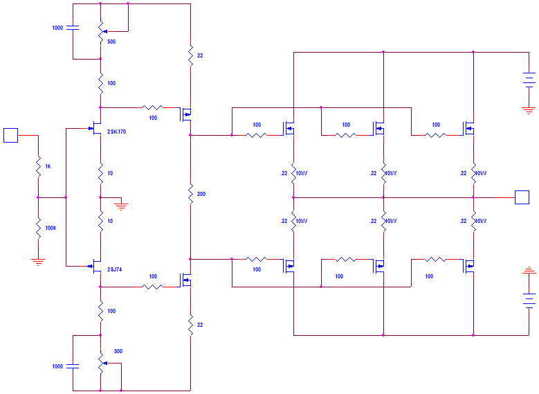
Guess the front end needs some power too...
The bias current resistor should be variable one way or another; R200 becomes P1. Or use a TL431 setting like in BA2 output.
And - - - have a DC point as this is floating now. Instead of DC feedback to the input sources, it is also possible to connect the speakers to a pair of capacitors of say 10.000 muF to both rails.
F4 variation
I haven't built this yet, so I don't know if it works. I am curious to see how much the 220uF coupling caps affect the sound, probably not much and easier to find out the 'cap sound' by fitting one to the input of an F5 - but the cap wouldn't have a bias voltage as it does in the F4. Anyway, this is my brain fart, the 1M and 1uF at the input can be dispensed with, and some of the values may need tweaking. Can't help feeling I've over looked something, I'm sure someone will point it out.
I haven't built this yet, so I don't know if it works. I am curious to see how much the 220uF coupling caps affect the sound, probably not much and easier to find out the 'cap sound' by fitting one to the input of an F5 - but the cap wouldn't have a bias voltage as it does in the F4. Anyway, this is my brain fart, the 1M and 1uF at the input can be dispensed with, and some of the values may need tweaking. Can't help feeling I've over looked something, I'm sure someone will point it out.
Attachments

gate zeners , as $#@!! Hapenning Preventers ?
in fact -= everything is OK , as long you're staying cool with input sine
in fact -= everything is OK , as long you're staying cool with input sine
gate zeners , as $#@!! Hapenning Preventers ?
I don't have the correct symbol, It represents a TL431.
everything is OK , as long you're staying cool with input sine
Thank you ZM.
I left out the input bootstrap for clarity.
I must be getting old, any more than 5V RMS output is too loud

- Home
- Amplifiers
- Pass Labs
- F4 power amplifier