My gut would have been that those heat sinks are good for half the heat you have. I'll be interested to see the temp after the lid is installed and it is on for 12 hours or so. Good luck!
My gut would have been that those heat sinks are good for half the heat you have.
I'm afraid you could be right. How should I go about taking their temperature? Should I be able to use something like a meat thermometer, or do I need something more specialized?
My gut would have been that those heat sinks are good for half the heat you have.
Not to dwell on this, but they may have appeared to be slightly smaller than they are. They are 10.75" L x 2" W x 6.5" H. I suppose they aren't very deep or thick, but that seems to be a fair amount of area.
Okay, I will stick with the hand test.
And the hand test weighs in at one second. I may need to readjust the bias on the lower channels. I noticed that when I raise it, the hum in the transformers increases, and only one of them is humming loudly. And it was set right as the batteries on my multimeter were running out.
Anyone have any suggestions for where I could get better heat sinks that would fit there?
Anyone have any suggestions for where I could get better heat sinks that would fit there?
Finally got around to getting things buttoned up. That buzz, has totally gone away and returns at a nearly undetectable level once it warms up for 12 hours or so.
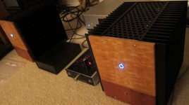
I'm curious if the F4 will drive what's behind garage door #1 in the second picture
I'm curious if the F4 will drive what's behind garage door #1 in the second picture
Attachments
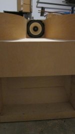
Nice cabinets in progress!
Thanks!
I have a feeling I'm about to have to go read Pano's gain structure thread. But, the upside is, I can probably just use a "regular" preamp and be fine.
I guess I could also try a swamping resistor across the drivers. Getting very close to being about to listen!
I have been using the HFA15TB60PBF in Solid state equipment for a long time and in the applications I used them in there were no artifacts of nasty Diode switching and a scope across the Diode confirmed this.
I have been thinking of using these in some Tube circuits for Biasing, as opposed to the Conventional diodes. if anyone has used these in this application your View would be real helpful TIA.
I have been thinking of using these in some Tube circuits for Biasing, as opposed to the Conventional diodes. if anyone has used these in this application your View would be real helpful TIA.
Is there any reason to try adding a swamping resistor across my DX4 TP1 / F4 combo? I can think of a few cases (transformer coupled amp maybe?) that this might make sense, but not sure if it is worth trying in my case.
well - you can do that with some intention ........
but - which one ?
Better sound? Better low end bass? Sanity that I tried something? 🙂
Can we play with harmonic distortion character (2nd/3rd ratio) of F4 by putting P3 (200 Ohm) over R3 and R4 (source resistors of JFets), like we do in case of F5 ?
presumably not , at least not in same amount - just because that's buffer stage - without voltage gain
The output devices are recommended to be Vgs matched +/- 0.02V -- but the gm of the two halves may be different -- in which case adjusting the source resistors on the MOSFETs may have some benefit -- but you've got 3 on each side so it will be a real headache!
Proper answer to my question can be found in the Nelson article
http://www.firstwatt.com/pdf/art_sweet_spot.pdf page 14 -15.
Yes you can change amount of distortion by trimming value of Jfet source resistors.
But change is not so dramatic in absolute numbers. So Zen Mod is right about it.
http://www.firstwatt.com/pdf/art_sweet_spot.pdf page 14 -15.
Yes you can change amount of distortion by trimming value of Jfet source resistors.
But change is not so dramatic in absolute numbers. So Zen Mod is right about it.
Last edited:
Choky is always right !
He knows everything about pass amps, don't forget, he's Papa's son
Audiofanatic 😉
Proper answer to my question can be found in the Nelson article
http://www.firstwatt.com/pdf/art_sweet_spot.pdf page 14 -15.
Yes you can change amount of distortion by trimming value of Jfet source resistors.
But change is not so dramatic in absolute numbers. So Zen Mod is right about it.
He knows everything about pass amps, don't forget, he's Papa's son
Audiofanatic 😉
Not being willing to read 51 pages of blurbs, I'll just ask--
1. Are Cs 1 and 2 signal-coupling capacitors?
2. If so, what is the load impedance for filter-point calc?
3. Can the cap-value be changed to create a hi-pass filter in the audible range for a speaker that requires one? That speaker is a Vandersteen 5A that needs a filterpoint between 50 and 100 Hz.
Thanx much in advance to the much-more-knowledgable-than-I (and that doesn't take much) who answer.
- Home
- Amplifiers
- Pass Labs
- F4 power amplifier