culture said:kroonsteentjes
Izza called : Euro terminal strips, Euro terminal block/mini block
jleaman said:
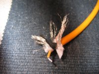
That cable should fit into your rca's might have to use a drill / dremel to open the end part a little, i had to once do that, where did you get that bright yellow rca cable ? got a picture of the tip so we can see the inside ?
Jase
Hi Jase
I bought the cable at speaker & co, a speaker diy shop (www.speakerenco.nl, it a dutch site), it cost 19 euros per meter 🙁
It was one of those "i want to have that moments" witch is highly capable of shutting down all sensibility in my brain. But i have to say the cable looks really nice, it's balanced and has tho shielding layers
http://www.vandenhul.com/p_B09.aspx
cheers,
c.
Attachments
Hi,
I am just about to start building a pair of F4's, and I am not sure reading through the posting just what circuit is the cannonical one now, I have found a R0 dated 17-04-2007, with 10R and a 100nf cap above the JFET, and 22R1 below. Another from the f4-amp.pdf, with 10R below the jfet. And I have seen posting from np, for a F4R0.pdf that doesn;t seem to exist in the posted place anymore.
Can someone point me to what sconsidered the current version please?
Thanks in advance
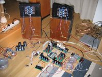
Well a half successful day today.. yesterday the bridge rectifiers beat me.. i couldn't get them properly wired up so today i bought myself a 100 watt soldering gun and that did the job... psu ready!
so i wired up the first channel and turned up the voltage bit by bit with the variac.. somhow i couldn't get the dc get the dc offset properly adjusted, it ran away constantly and the stuff got really hot.. so i tried the second channel, dc offset was set straight away and to set the bias no problem. so after that i connected my i pod and a speaker and yes... music!!!! back to the first channel.. well things didn't get any better.. every time i cranked up the voltage the dc offset ran away... the fets on this channel got much much hotter than on the other channel.
I measured the resistance between v+ and gnd and that is about 2 or 3k.. same between v- and gnd. on the working channel i measure 300k...
i will look into it tomorrow and hopefully findout what the problem is, lucky enough i have enough spare parts...
hopefully some bright minds here on the forum can give me some good suggestions where to look and what to do.. but for now.. bed time!
cheers,
c.
F4 r0 diff
I have a questione as below and what is the different?
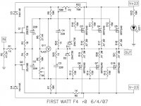
1. the F4 r0 dated 4/17/07 is R3,R4=22R1 and R10-R15=100R.
2. the F4 r0 dated 6/4/07 is R3,R4=10R and R10-R15=150R.
I have built two channel for F4 r0 dated 4/17/07 already and now will build another two channel, so i would like to know the differece between these two.
I have a questione as below and what is the different?
1. the F4 r0 dated 4/17/07 is R3,R4=22R1 and R10-R15=100R.
2. the F4 r0 dated 6/4/07 is R3,R4=10R and R10-R15=150R.
I have built two channel for F4 r0 dated 4/17/07 already and now will build another two channel, so i would like to know the differece between these two.
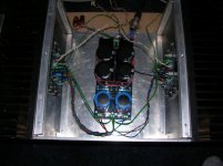
found the problem!!
same problem as i had with my p1.7..... wrong resistor. i used a 10 ohm resistor for r9 instead of 10k.... well, no damage was done and the system is playing now..
but what a sound!!!!! and i'm only listening to mp3s (still need to make the interlinks).. cant wait to hookup my pearl or my cd player and see what that brings 🙂
oke, time to cook me some dinner now and enjoy some class-a ipod music 🙂
cheers,
c.
Attachments
Maybe you would also care to share with us what you had heard before the F4 ?
Cheers,
Patrick
Cheers,
Patrick
F4 burning in test
Hello guys, finally i spare some time to solder parts on my F4 and screw it on proper heatsinks. so i went to the university lab to test it.
Since Amplimo toroidal isn't arrived yet, i have tested it with regulated bench psu, rated for +/- 30V 6A.
The bias point was set at 1,25 A per side.
Well, it seems to have a certain dc offset vs temperature drift, about 50mV from 25°C to 60, i wonder if it's normal?
The function generator can swing 7,8V RMS and i cannot take F4 to it's clipping point, it shows clean sine wave until 100Khz... wow it works 😀
but i guess there's something wrong with the square wave response...
the output shows and important overshoot (about 2V with 7,8V RMS input) then it reach the square wave value very fast, oscillating around it. I cannot explain myself well, here's a pic that could explain it better:
http://www.serenoeditore.com/tecnologie/equa8.jpg
In my setup the decay of the oscillation is about 1/5 of the half period (not half period as shown).
Do you guys have any thoughts about that?
all the best,
Marco
thanks for your answer!
the SW shows overshooting @ any freq i've tried, something between 1K and 100K, the load was a 10ohm 10w resistor.
the SW shows overshooting @ any freq i've tried, something between 1K and 100K, the load was a 10ohm 10w resistor.
Have you tried decoupling your psu with some large psu caps? How does the rails look when you see this overshooting?
I build the first revision published here, and it sounds great, but feeded from the jfet boz, the top end sounds very harsh - I hope this is not just the sound of the overshoot you have measured...
I build the first revision published here, and it sounds great, but feeded from the jfet boz, the top end sounds very harsh - I hope this is not just the sound of the overshoot you have measured...
i tried some on-the-fly tests only, sorry no caps were used as decoupling but psu dc output was ok.
I built mine according to the latest schematic and set R9 to 6,8K (with 10K i cannot go higher than 200mA per Fet)
honestly i don't know why that overshooting nor if this could be a matter soundwise...
I built mine according to the latest schematic and set R9 to 6,8K (with 10K i cannot go higher than 200mA per Fet)
honestly i don't know why that overshooting nor if this could be a matter soundwise...
In my initial planning stages for the F4. Am still learning at this stage - this will be my fourth project.
Noticed that some people are using the MUR 3060 diodes for the rectification - while others are using the single component bridge rectifiers (is that how you call it?) - any difference (sonically, safety, reliability) to these two approaches?
Looking at the power supply schematic - R9&R10 are bleeder resistors to drain the caps after shut down? I guess for safety sake it is better to include them - correct me if I'm wrong.
That's all for now.
thanks
her shann
hershann said:Noticed that some people are using the MUR 3060 diodes for the rectification - while others are using the single component bridge rectifiers (is that how you call it?) - any difference (sonically, safety, reliability) to these two approaches?
Looking at the power supply schematic - R9&R10 are bleeder resistors to drain the caps after shut down? I guess for safety sake it is better to include them - correct me if I'm wrong.
The ordinary 35A/1000V bridge rectifier is fine on my experience.
Yes, they are bleeders. Why not?

offset reversed 12.16v dc
Hello, just finishing my F4 proyect and trying to set it up.
No problem setting the bias, there are 200mv across the power resistors (all of them)
The problem is that I read -12,16v dc on the speaker outputs (input shorted and no load on the amp). The voltage is reversed, touching the output from the F4 with the red wire of my multimeter and the ground on the PSU with the black wire gives me a read of -12,16v dc.
I have been playing around with p2 and nothing happens, -12,16v all the time. I have the same problem on both channels.
Help please!
Thanks in advance.
- Home
- Amplifiers
- Pass Labs
- F4 power amplifier