That is great work.
You've made some excellent progress.
Transformer temp seems ok considering the likely internal chassis temperature.
You've made some excellent progress.
Transformer temp seems ok considering the likely internal chassis temperature.
Could I mount the PS board above the transformer?
I don't have a shelf angle right now, but that's another consideration. Thanks!
I would want some additional shielding, like some kind of steel box over the transformer, then Bob's your uncle. Or even some Square or Rectangular Hollow section steel with the transformer mounted inside (with the openings of the sectioned steel to the sides of the chassis, or in the most appropriate direction to get the best level of shielding depending on layout).
Last edited:
Working on improving routing, Jim. The 4U chassis is tight with a 600 VA trafo.
Pico, the 4U chassis is more wide than long, so layout is becoming tight. Have to put the bridges to the side of the transformer AND away from the PS board. Then have to route wires from the sides to the PS board. Could I mount the PS board above the transformer?
I don't have a shelf angle right now, but that's another consideration. Thanks!
Transformer top plate was at 45 C I think after a good 4 hours. Transformer felt cooler than that.
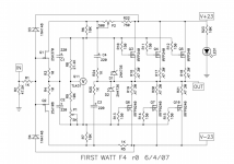
Grounding is as per the FW supply circuit. Only place signal ground meets earth is at the chassis and there is a thermistor providing a small voltage barrier between signal ground and chassis/earth.
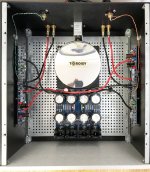
Have a look at the attached photo. You need to be careful with the PCB placements and the length of important wiring.
The mains wiring (most important; has to be shortest possible AND placed very close to the chassis- away from all other parts/wiring) is 10cm long, that INCLUDES the CL60 which I mounted on the IEC RF filter lugs. There is no need to use the terminal block at all.
The DC rails wiring is also minimised (also very important... for the sound quality) because the power supply board is "turned around". I also used a very thick wire here, and the pure copper round lugs that I managed to feed into AMP PCB eyelets.
The non-important wiring, which is the secondary AC wiring, is actually the longest here; it is tucked underneath the transformer base plate and the power supply PCB. Twist each windings' wires tightly.
This is an old photo... I moved to a balanced config a few months ago, which helped remove the mains buzz/hum I had to tame with the 10ohm ground-break resistor. The amp is now completely quiet without the resistor.
Attachments
Last edited:
Made some progress today.
One more thing to check brother.
This is bloody important actually.
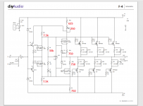
Ideally you want a 13V drop (or larger) across R6 and R7. I am assuming you used the standard version of TL431.
Measure that.
Attachments
Last edited:
No, I am measuring 9.85 V or so in both channels and both resistors.
This is the one I used:
TL431BVLPRAG ON Semiconductor | Mouser
This is the one I used:
TL431BVLPRAG ON Semiconductor | Mouser
Extreme_Boky, wow, that is amazing. Thanks for sharing. Good points regarding layout.
I'm thinking of getting a trafo cover myself. Antek is selling a cover for their transformers. I'm going to look into it. I believe the transformer being so close to the DC wiring is where the problem lies. And there is no layout I can think of where the transformer will be far enough away from the PS board, and especially the middle of the PS board.
I'm thinking of getting a trafo cover myself. Antek is selling a cover for their transformers. I'm going to look into it. I believe the transformer being so close to the DC wiring is where the problem lies. And there is no layout I can think of where the transformer will be far enough away from the PS board, and especially the middle of the PS board.
Last edited:
No, I am measuring 9.85 V or so in both channels and both resistors.
This is the one I used:
TL431BVLPRAG ON Semiconductor | Mouser
This should be fixed.
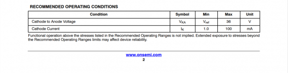
This particular device requires a minimum of 1mA cathode current to operate correctly plus you have an additional 0.25mA going through the programing resistors. So you should have a 12.5V drop across those 10k resistors bare minimum.
Maybe replace them with TLVH431 these operate at much lower cathode currents, or change the jfets with lower idss devices or other adjustments.
Proper operation of the shunt regulator will affect PSRR of your amp as proper bias control.
Attachments
Last edited:
I have a tl431clpm from 2010. It is actually in a sealed bag from digikey. Lol. Would these work?
I had no idea there were different versions of TL431. The diyaudio BOM does not specify a version. Maybe we should change it.
I had no idea there were different versions of TL431. The diyaudio BOM does not specify a version. Maybe we should change it.
Last edited:
I am confused, is that attached picture shows values 1-100mA for a device appropriate for F4?
All ON devices from have 1-100:
Search results for: tl431bcl Voltage References – Mouser
Those are not appropriate for the circuit?
All ON devices from have 1-100:
Search results for: tl431bcl Voltage References – Mouser
Those are not appropriate for the circuit?
Last edited:
Should I be getting 2.5 V across R9 and P1? Would that tell me if the current TL431 is working correctly? It is tight in those spaces, but will try to measure.
Edit: there is 1.56 V across the R9 and P1. That should be 2.5 V, yes?
The CLPM version has less current requirement and I have it, so I can try it. Though, I hate to perform surgery on the board and in a tight area.
Edit: there is 1.56 V across the R9 and P1. That should be 2.5 V, yes?
The CLPM version has less current requirement and I have it, so I can try it. Though, I hate to perform surgery on the board and in a tight area.
Last edited:
Edit: there is 1.56 V across the R9 and P1. That should be 2.5 V, yes?
Yeah. You should measure 2.5V
You have a problem with your shunt. You need more current. This should further improve things quite a bit.
TLVH431 will operate with 100uA. You could try that. There are some other that operate with lower current.
I am confused, is that attached picture shows values 1-100mA for a device appropriate for F4?
All ON devices from have 1-100:
Search results for: tl431bcl Voltage References – Mouser
Those are not appropriate for the circuit?
It is appropriate but only if you're jfets don't draw too much current.
To be on the safe side TLVH431 would be a better device as it will operate at much lower currents.
Last edited:
Yeah a steel L Bracket with the transformer in a steel can. Maybe one of those Antek steel cans would work.
I have a tl431clpm from 2010. It is actually in a sealed bag from digikey. Lol. Would these work?
This one also requires at least 1mA, so that won't work either.
Ok here is another good one
This will operate with a cathode current from as low as 40uA according to the datasheet.
http://www.digikey.com/product-detail/en/on-semiconductor/NCP431ACLPRAG/NCP431ACLPRAGOSCT-ND/3929329
http://www.onsemi.com/pub/Collateral/NCP431-D.PDF
This will operate with a cathode current from as low as 40uA according to the datasheet.
http://www.digikey.com/product-detail/en/on-semiconductor/NCP431ACLPRAG/NCP431ACLPRAGOSCT-ND/3929329
http://www.onsemi.com/pub/Collateral/NCP431-D.PDF
Last edited:
Ok one more.
Always good to have more than one choice.
http://www.digikey.com/product-deta...ed/AP431SAZTR-G1/AP431SAZTR-G1DICT-ND/6674259
Always good to have more than one choice.
http://www.digikey.com/product-deta...ed/AP431SAZTR-G1/AP431SAZTR-G1DICT-ND/6674259
thank you so much! Order all of them, now will have an anxiety what to start with hehehe 🙂 Suggestion?
What is your question regarding indecision?
The diodes one has an output impedance of 0.1 Ohms so possibly that is better, but these specs are usually worst case scenario etc so in reality they may not be actually any different, kind of depends on the manufacturer how they decide to specify their parts some may give conservative specs and others not so conservative.
Kind of like the XA30.8 rated at 30W, this is a very conservative rating as it can actually swing much higher voltages than a 30W amp.
The same applies to many components, the data sheet is not always super accurate or they specify for worst possible parts in a batch not the average.
They are all good.
I will look at the data sheets more closely to see if anything sticks out as being superior.
Last edited:
- Home
- Amplifiers
- Pass Labs
- F4 power amplifier