That is good to know. I was beginning to infer that from many of your previous remarks.
What is your current feeling about the H2 vs. H3 level (at the output) in the zero degeneration amps where the higher order harmonics fall off very rapidly? At a mid-level power would you want H2 much larger than H3? Do you have a criterion about when it is necessary to "tune" H2/H3 of the OS?
Zero degeneration is still such a novelty that we haven't come to much
of a consensus about what the desired relative levels are.
There is a tradition that dominant 2nd is preferred, but I have spent
pleasant time with positive phase 2nd, negative phase 2nd, and 3rd
harmonic, and there are well regarded examples of each.

I was talking about normally degenerated stages. The lack of it adds another dimension of tweaking and listening tests to do. To which degree i have no idea.
I was talking about normally degenerated stages. The lack of it adds another
dimension of tweaking and listening tests to do. To which degree i have no
idea.
The sound without degeneration is different, particularly on the output
stage. It does cause a re-evaluation, but then that's where the fun is.
🙂
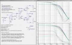
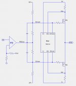
While waiting for my new power supplies I couldn't resist more simulations. I am still trying to understand the effect of load resistance on the distortion spectra. Below is a test circuit for undegenerated output fets, using an "ideal" front-end (FE).
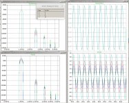
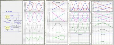
The first set of plots shows the distortion spectra for 1kHz, 1W, and 20dB feedback with four values of Rload: 2R, 4R, 8R, and 16R. The top row is normalized V(Out) so that the fundamental is at 0dB for all loads.
The second set of plots shows the test circuit and the AC response for all four load resistances. The top AC response curves for phase, whereas the bottom curves show group-delay. I find the group-delay plot to be very interesting.
Attached is the .asc file and a file containing the LTSpice .fourier log numbers.
Attachments
Last edited:
Usually my go-to approach. I find that the output stage is the best
(if not easiest) place to play with the symmetry.
Without adjustment, the FE will have some amount of second harmonic (H2). There are many possible ways to make such an adjustment, including the choice of JFETs. What are the "proper" conditions for measuring the neutrality of the FE? one approach is to connect the feedback resistor to the FE output rather than the OS output and adjust the harmonic spectrum of the FE output. Should the FE be loaded by the OS FET gates when making such measurements?
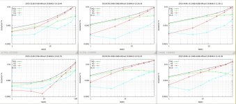
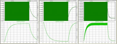
I started bench measurements about a week ago and discovered problems with distortion measurements because of the change of output FET bias with power and load resistance. After modifying my software for distortion measurements I was able to capture the output signal faster before the bias changes significantly. Below are some results.
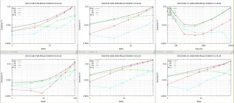
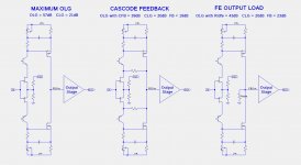
These distortion sweeps are for 3 different configurations, shown left to right:
These distortion sweeps are for 3 different configurations, shown left to right:
- maximum feedback
- feedback limited using cascode feedback
- feedback limited using a load resistor on the FE output
Attachments
Based on both simulations and bench measurements of long signal bursts (30 secs), both the the series optocoupler and parallel optocoupler bias circuits have a significant drift in bias as the power is increased or the load resistance is reduced. Bias increases with the series circuit and decreases with the parallel circuit.
Below is a hybrid of the series and parallel bias circuits that significantly reduces the drift. For 25 Watt signals into 4R and 8R loads, the drift is reduced to about 6mA.
Below is a hybrid of the series and parallel bias circuits that significantly reduces the drift. For 25 Watt signals into 4R and 8R loads, the drift is reduced to about 6mA.
Attachments
The high feedback measurements in the left column are best, and I have been listening to this configuration for many months. Sounds great! I have not seen any stability problems due to the high feedback.which one you prefer?
I have not listened to either of the other two versions, and it would probably require building a complete amplifier in order to do A/B comparisons between two versions at a time.
My speakers have a nominal impedance of 8 Ohms. They are the Jeff Bagby designed Kairos using SB Acoustics Satori MW16P woofers and TW29R tweeters.your speakers are 8 or 4R?
In post #1510, I forget to mention that the resistor values for Rcsp and Rcss must be carefully adjusted to achieve the cancellation of the opposing bias current drifts and the desired bias current.
I just noticed that the distortion sweeps in the upper right corner in post #1508 was the Frequency sweep rather than the the Watts sweep. Here is the corrected set of sweeps. Notice how similar the cascode feedback and FE load versions are for both 4R and 8R loads.
Attachments
Based on both simulations and bench measurements of long signal bursts (30 secs), both the the series optocoupler and parallel optocoupler bias circuits have a significant drift in bias as the power is increased or the load resistance is reduced. Bias increases with the series circuit and decreases with the parallel circuit.
Do you know why the bias drifts with power and load resistance? Has it to do with leaving class A or is some other factor responsible? I can see that your series/parallel combination will work but it would nice to avoid the additional complexity if at all possible.
The bias drift vs. load resistance is easy to explain. For a given output power the fet current range increases as the resistance is lowered. The remaining question is why the bias changes as the FET current range increases. It is apparently due to the increasing asymmetry of the FET current waveforms as the current increases. The behavior is the different for the serial and parallel opto configurations. In the series configuration, at higher current levels (more asymmetric) the time integrated current output from the servo is insufficient and thus the voltage V(drive+,drive-) increases. In the parallel configuration the opposite occurs.
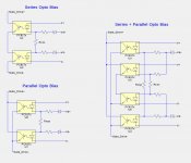
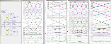
The images below show:
The images below show:
- circuit topology
- series optocoupler servo and waveforms
- parallel optocoupler servo and waveforms
- hybrid optocoupler servo and waveforms
- servo circuit
- 1 W waveforms vs. time
- 1 W waveforms vs. V(Out)
- 1W and 25W waveforms vs. time
- 1W and 25W waveforms vs. V(Out)
- FET currents
- LED currents
- Opto transistor currents
- V(Drive+,Drive-) total bias voltage
Attachments
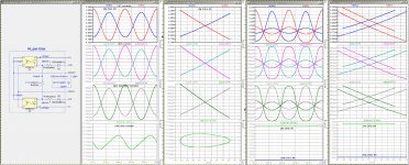
Here is another presentation of the behavior of the 3 servo configurations. Shown is ar the FET currents (top) and V(Drive+,Drive-) total bias voltage for a 30 second duration 20Hz 25W pulse into an 8R load. From left to right are the series, parallel, and hybrid configurations. Note the vertical scales in the plots. The bias drift for the hybrid configuration is less than 3mA.
Attachments
which one you prefer?
The other considerations about the level of global feedback around the output stage are the damping factor and slew rate.
Since I have not listened to the lower feedback versions of the circuit I cannot offer any opinion. I know from 7 months of listening that the high global feedback version sounds excellent.
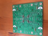
Very nice artwork! Real Firstwatt, Papa's style.
This is my version of the frontend, kind of UGS - Sony VFET pt2. Learning how to use Kicad finally pays off. I can configure this PCB in many ways to experiment. With or without degeneration of the small MOSFETs, EUVL trick for the JFET's or no degeneration at all. Balanced or left - right frontend.
Swiss army knife...
I will experiment with different output stages. But I think I will build this one Generg gave us first.
Did you actually build it? Instead of using many paralleled IRFP240's, using two hockey pucks will be nice to try.
Thanks to Walter who shared with me 2pcbs I managed to build 2 balanced channels that I intend to use as a preamp after a dac.
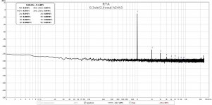
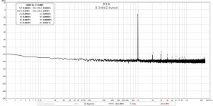
I did some thd measurements on the run and did get very impressed by the results.
My goal was not to get the lowest thd but to see if I can tune h2/h3.
Attachments

- Home
- Amplifiers
- Pass Labs
- F4 Beast Builders