Wow, both plots look really impressing! Can you also go with positiv and negative phase to get the same H2/H3 relations?
Regards, Matthias
PS: Which software are you using, and which soundcard?
Regards, Matthias
PS: Which software are you using, and which soundcard?
Nice to see 😀
How are you changing the H2 and H3? By modifying the source resistors of the JFET's or MOSFET's?
How are you changing the H2 and H3? By modifying the source resistors of the JFET's or MOSFET's?
Wow, both plots look really impressing! Can you also go with positiv and negative phase to get the same H2/H3 relations?
Regards, Matthias
PS: Which software are you using, and which soundcard?
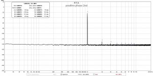
Yes you can tune h2/h3 to be positive or negative
I am using focusrite 2i2 soundcard and rew software
Nice to see 😀
How are you changing the H2 and H3? By modifying the source resistors of the JFET's or MOSFET's?
I am changing the harmonics by adjusting the load lines of the jfets(the pots placed in the collector of the cascodes)
Attachments
Stirring the pot again:
I am thinking about an amplifier with the XA25 IXYS OS combined with a vacuum tube FE. The pairing could be really good since the capacitances of the IXYS FETs are so low when running as a PP source follower stage. I have been making measurements of FE and OS of an amp similar to the XA25 and find that the FE seems to contribute most of the distortion. With lots of feedback, like the XA25, the result is excellent, but some form of triode front end might be even better.
I am thinking about an amplifier with the XA25 IXYS OS combined with a vacuum tube FE. The pairing could be really good since the capacitances of the IXYS FETs are so low when running as a PP source follower stage. I have been making measurements of FE and OS of an amp similar to the XA25 and find that the FE seems to contribute most of the distortion. With lots of feedback, like the XA25, the result is excellent, but some form of triode front end might be even better.
Stirring the pot again:
I am thinking about an amplifier with the XA25 IXYS OS combined with a vacuum tube FE. The pairing could be really good since the capacitances of the IXYS FETs are so low when running as a PP source follower stage. I have been making measurements of FE and OS of an amp similar to the XA25 and find that the FE seems to contribute most of the distortion. With lots of feedback, like the XA25, the result is excellent, but some form of triode front end might be even better.
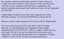
Which particular IXYS pucks are you using? I thought that the input capacitances are in the nF range and require more current than the IRFP MOSFETs to drive.
It would be useful to know exactly how much current is required to drive these pucks.
I am using IXFN140N30P and IXTN40P50P IXYS FETs. Look at the Crss curves in the datasheets and consider Nelson's comments about Crss and input capacitance in follower stages. Mosfet Output Stage Capacitance I seem to recall a BAF talk by Nelson which mentions the utility of the low Crss of a particular IXYS FET.
What Spice model are you using for IXFN140N30P? There doesn't appear to be one on the ISYS web site and it is not easy to tell whether there are others that are reasonably close.
I am using IXFN140N30P and IXTN40P50P IXYS FETs. Look at the Crss curves in the datasheets and consider Nelson's comments about Crss and input capacitance in follower stages. Mosfet Output Stage Capacitance I seem to recall a BAF talk by Nelson which mentions the utility of the low Crss of a particular IXYS FET.
Thanks for the link. I will give that a try. It crossed my mind a couple of weeks ago to use a DMM to measure the AC voltage across the gate stop resistor. Nelson's idea to measure loaded and unloaded is a very nice touch to separate the two capacitances.
It might require a higher values gate stopper resistor in order to be able to measure the voltage drop. It might be better to use the technique for measuring input capacitance shown here http://www.firstwatt.com/pdf/art_mos_test.pdf.Thanks for the link. I will give that a try. It crossed my mind a couple of weeks ago to use a DMM to measure the AC voltage across the gate stop resistor. Nelson's idea to measure loaded and unloaded is a very nice touch to separate the two capacitances.
It might require a higher values gate stopper resistor in order to be able to measure the voltage drop. It might be better to use the technique for measuring input capacitance shown here http://www.firstwatt.com/pdf/art_mos_test.pdf.
Noted. I will try both methods and post some results. I also have occasional access to a CV measurement system and will save some tests and post those.
It will be a while as the day job is keeping me on the road quite a bit this year.
I thought more about using a DIMM for measuring FET input capacitance. It probably will not be accurate since most DIMMs cannot make accurate AC measurements at the high frequencies. Also, the parasitic capacitances of the DIMM leads and internals will introduce errors. An oscilloscope could work, but a differential measurement is required with a big common-mode component. It is probably much better to infer the capacitances from the output response vs. frequency.Thanks for the link. I will give that a try. It crossed my mind a couple of weeks ago to use a DMM to measure the AC voltage across the gate stop resistor. Nelson's idea to measure loaded and unloaded is a very nice touch to separate the two capacitances.
Can you provide a link to "Nelson's idea to measure loaded and unloaded"? I looked around but could not find it.... Nelson's idea to measure loaded and unloaded is a very nice touch to separate the two capacitances.
Can you provide a link to "Nelson's idea to measure loaded and unloaded"? I looked around but could not find it.
Attachments
Stirring the pot again:
I am thinking about an amplifier with the XA25 IXYS OS combined with a vacuum tube FE.
I had a similar idea, except I intend to use the LU1014 to act as a very low distortion triode.
I also plan to SUSY this idea with a 2SJ74 differential pair on the input...
If only summer would arrive.
LU1014 is an interesting alternative with the advantage of not needing extra power supplies and all of the other things that come with tube circuits.I had a similar idea, except I intend to use the LU1014 to act as a very low distortion triode.
I also plan to SUSY this idea with a 2SJ74 differential pair on the input...
If only summer would arrive.
I am still analyzing and redoing various bench tests to better understand the IXYS OS and how the FE and feedback factors affect the resulting performance.
I need to repackage my PCBs so that the OS and its bias circuits are better separated from the FE so that experiments with different FE designs are easier. This would be an F4 type PCB design using a single pair of IXYS FETs, and a BA3GS type PCB for the FE. One possibility is a motherboard for the OS and daughter board for the FE.
Last edited:
I need to repackage my PCBs so that the OS and its bias circuits are better separated from the FE so that experiments with different FE designs are easier. This would be an F4 type PCB design using a single pair of IXYS FETs, and a BA3GS type PCB for the FE. One possibility is a motherboard for the OS and daughter board for the FE.
That would be very cool. I have built a DIY Store BA3 FE board recently. The particular Toshiba driver transistors I have produce a gain of 10-ish which may be a bit light after applying enough feedback for the complete amplifier.
Simply take instead of the low 330R load resistor for instance 1k as load or even higher and you might have enough OLG for a good feedback loop.
What Spice model are you using for IXFN140N30P? There doesn't appear to be one on the ISYS web site and it is not easy to tell whether there are others that are reasonably close.
Did you find a Spice model for this?
Martin
- Home
- Amplifiers
- Pass Labs
- F4 Beast Builders