Here is the SPICE model I am using for the XFN140N30P. It was cobbled together from other IXYS models and bench measurements of my FETs. I have no idea how good it is, but for many things the model compares well with actual measurements.
.model IXFN140N30P VDMOS(nchan Vto=4.03 Kp=4.15 Lambda=4.3m Rs=2.2m Rd=0.17 Rds=1e7
+ Cgdmax=4nF Cgdmin=50pF a=0.35 Cgs=13nF
+ Cjo=35nF m=0.75 VJ=2.5 IS=4.0E-06 N=2.4 ksubthres=.22)
.model IXFN140N30P VDMOS(nchan Vto=4.03 Kp=4.15 Lambda=4.3m Rs=2.2m Rd=0.17 Rds=1e7
+ Cgdmax=4nF Cgdmin=50pF a=0.35 Cgs=13nF
+ Cjo=35nF m=0.75 VJ=2.5 IS=4.0E-06 N=2.4 ksubthres=.22)
Here is the SPICE model I am using for the XFN140N30P. It was cobbled together from other IXYS models and bench measurements of my FETs. I have no idea how good it is, but for many things the model compares well with actual measurements.
.model IXFN140N30P VDMOS(nchan Vto=4.03 Kp=4.15 Lambda=4.3m Rs=2.2m Rd=0.17 Rds=1e7
+ Cgdmax=4nF Cgdmin=50pF a=0.35 Cgs=13nF
+ Cjo=35nF m=0.75 VJ=2.5 IS=4.0E-06 N=2.4 ksubthres=.22)
Thanks!
Here are some interesting spectral plots from LTSpice. They are simulations of an OS using the IXFN140N30P and IXTN40P50P FETs, driven by a "perfect" front end whose output impedance is 1K and whose open-loop gain (OLG) is a parameter derived from the closed-loop gain (CLG) and feedback factor. For this simulation CLG=10x (20dB). Shown are spectral plots for 5W and 25W output into an 8R load. What is interesting is that with a "perfect" FE, meaning that the FE introduces no distortion components of its own, the harmonic falloff with frequency remains the same as the feedback factor is increased. This seems to contradict the usual concern that higher feedback factors cause the higher harmonics to increase in relation to H2 and H3.
Attachments
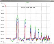
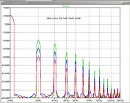
This seems to contradict the usual concern that higher feedback factors cause the higher harmonics to increase in relation to H2 and H3.
They still do, but this is only significant when the open loop distortion is
quite high, like more than 1%, and usually noticed only when there
weren't significant high order harmonics already.
In your example, those harmonics are already there, and your open
loop distortion numbers are pretty low.
"Defenders" of negative feedback correctly point out that this is not
an issue if the distortion is fairly low to start with, not to mention that
the distortion of all kinds is still being reduced.

The reason I was examining the role of the perfect FE and the feedback factor was to establish a baseline for what might be the best that can be expected from an imperfect FE and what the harmonic falloff pattern could be for the best case.
If there are "tuning" parameters for the imperfect FE, such as the H2 level and phase, perhaps the baseline harmonic profile would be a good guide for "tuning" the FE.
If there are "tuning" parameters for the imperfect FE, such as the H2 level and phase, perhaps the baseline harmonic profile would be a good guide for "tuning" the FE.
Perhaps. Given that the output stage appears to generate relatively high order harmonics in the distortion spectra, it would seem some mechanism may be required to counteract it. Not sure whether "tuning" the FE will achieve this but certainly worth investigating.
Perhaps I didn't properly explain my objective for "tuning" the FE. What I am trying to do is adjust the FE so that global feedback through the FE doesn't increase (or minimally increases) higher order harmonics relative the H2 and H3. Simulations show that the "perfect" FE accomplishes that objective. An imperfect FE can be tuned to remove even order harmonics. An imperfect FE can also be tuned to lower all harmonics by using local feedback, such as cascode feedback.Perhaps. Given that the output stage appears to generate relatively high order harmonics in the distortion spectra, it would seem some mechanism may be required to counteract it. Not sure whether "tuning" the FE will achieve this but certainly worth investigating.
I misunderstood. So, your goal is to not have the FE degrade the OS performance as measured with a perfect FE.
I'm also guessing that you don't want to remove even harmonics, or at least k2 given that the intentionally mismatched OS FETs are chosen so as to provide more k2?
I'm also guessing that you don't want to remove even harmonics, or at least k2 given that the intentionally mismatched OS FETs are chosen so as to provide more k2?
I would not say the the OS FETs are intentionally mismatched. Yes, the OS produces a lot of k2 due to the transconductance mismatch of those FETs, but that is not why they were chosen.I misunderstood. So, your goal is to not have the FE degrade the OS performance as measured with a perfect FE.
I'm also guessing that you don't want to remove even harmonics, or at least k2 given that the intentionally mismatched OS FETs are chosen so as to provide more k2?
If you were to build a balanced (bridged) amplifier using the same FE and OS, you should be able to cancel the even harmonics, if that is what you really want.
Based on Nelson's comment in post #1545:
I realize that I chose an inappropriate example for studying the FE/OS feedback issues. The OS using IXYS FETs and an FE of Sony VFET-2 flavor have distortion too low to really exhibit the kind of harmonic mixing that cause problems with high levels of feedback.They still do, but this is only significant when the open loop distortion is quite high, like more than 1%, and usually noticed only when there weren't significant high order harmonics already.
At this point I do not know how the FE "tuning" will affect the sound of this amplifier. I need to build a complete second amplifier so that I can do A/B testing.
I would not say the the OS FETs are intentionally mismatched. Yes, the OS produces a lot of k2 due to the transconductance mismatch of those FETs, but that is not why they were chosen.
If you were to build a balanced (bridged) amplifier using the same FE and OS, you should be able to cancel the even harmonics, if that is what you really want.
At this point I do not know how the FE "tuning" will affect the sound of this amplifier. I need to build a complete second amplifier so that I can do A/B testing.
OK, now I am intrigued: why did you chose this particular pair of OS FETs?
Not saying that I personally want to cancel the even harmonics - I don't, or at least I am not pursuing this as a goal.
Agree with you regarding A/B testing and I look forward to reading about your results.
When using IXYS SOT-227B FETs, there are very few choices for the P-channel FET. The N-channel FET was chosen primarily for its low Crss values. Apparently PassLabs is using the IXFN140N30P in the XA25; look at the photos in the 6Moons review.OK, now I am intrigued: why did you chose this particular pair of OS FETs?
...
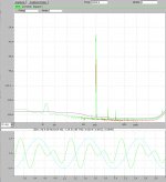
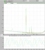
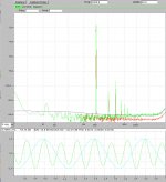
Here is a rather nice set of bench measurements where the closed-loop gain is 20dB, the global feedback is only 14dB. The open-loop gain with no load on the FE and no cascode feedback is about 57dB. The FE load resistor and cascode feedback reduce the open-loop gain to about 34dB. This is a good result, but the damping factor is significantly reduced, as would be expected from the reduced global feedback.
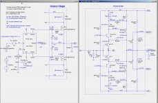
In the plots below show the harmonic spectra for 1kHz into 8R for 1W, 5W, and 20W, and the circuit.
In the plots below show the harmonic spectra for 1kHz into 8R for 1W, 5W, and 20W, and the circuit.
Attachments
-
 ZD25-20180426-GFB-Rldfe-1k-Rlfb-20k-CFBpot-1W-1kHz-Out-spectrum.jpg214.4 KB · Views: 674
 -
 ZD25-20180426-GFB-Rldfe-1k-Rlfb-20k-CFBpot-5W-1kHz-Out-spectrum.jpg221.7 KB · Views: 631
 -
 ZD25-20180426-GFB-Rldfe-1k-Rlfb-20k-CFBpot-20W-1kHz-Out-spectrum.jpg240.4 KB · Views: 670
 -
 ZDxx-lowolg-test-1b-20180426.asc.jpg294.1 KB · Views: 656
When using IXYS SOT-227B FETs, there are very few choices for the P-channel FET. The N-channel FET was chosen primarily for its low Crss values. Apparently PassLabs is using the IXFN140N30P in the XA25; look at the photos in the 6Moons review.
Isn't what the XA25 uses speculation? The 6Moons photo shows a somewhat ambiguous "40N30P" which of course does not exist. I appreciate that there are few P-channel devices but there are quite a few N-channel that I believe could be married to this. I was under the impression that it may be beneficial to mismatch gm in the OS so as to provide a similar sound (harmonic signature) to that of PassLab's SE bias arrangements in some of their other amplifiers. But then of course I could be completely wrong.
Here is a rather nice set of bench measurements where the closed-loop gain is 20dB, the global feedback is only 14dB. The open-loop gain with no load on the FE and no cascode feedback is about 57dB. The FE load resistor and cascode feedback reduce the open-loop gain to about 34dB. This is a good result, but the damping factor is significantly reduced, as would be expected from the reduced global feedback.
In the plots below show the harmonic spectra for 1kHz into 8R for 1W, 5W, and 20W, and the circuit.
Nice indeed which is reassuring given that it is very similar to what I am building 🙂 Just out of interest what is the damping factor in your case? Also are you using the series-parallel opto bias servo in yur bench measurements or something else? I've been searching for a simpler solution that can cope with the gm mismatch but I've yet to find one!
With 14dB global feedback, the damping factor is about 270 and this agrees well with the simulation results....
Just out of interest what is the damping factor in your case? Also are you using the series-parallel opto bias servo in yur bench measurements or something else?
...
BTW: I found an error in the simulation file in post #1554. RflbP2 should have been 28.7k and RlfbN2 should have been 31.3k.
The bench tests use the parallel bias servo, not the series-parallel hybrid. I have been very careful in my measurements to prevent the errors due the the bias changing during the measurement, by applying a short duration input signal, usually than one second. For low power (<=5W) levels the bias change does not appear to be significant, allowing the input signal to be applied for a longer duration, providing a lower noise floor in the power spectrum.
Sorry to burst my own bubble, but at low feedback factors the circuit is very sensitive to the load resistance.
I am working on a mathematical analysis of the push-pull equations combined with feedback. They can be pretty messy, but they could provide some insight into the issue of FET transconduction mismatch and k2.
I am working on a mathematical analysis of the push-pull equations combined with feedback. They can be pretty messy, but they could provide some insight into the issue of FET transconduction mismatch and k2.
Sorry to burst my own bubble, but at low feedback factors the circuit is very sensitive to the load resistance.
I am working on a mathematical analysis of the push-pull equations combined with feedback. They can be pretty messy, but they could provide some insight into the issue of FET transconduction mismatch and k2.
Is load resistance here at the OS output or elsewhere? I'm asking because I observed similar behaviour with variations in the FE load resistance when I was playing around with some simulations a while ago. At the time I didn't investigate further thinking it was probably some kind of simulation glitch but in retrospect perhaps this was not such a good decision.
Like ZM I do not enjoy performing messy mathematical analysis but I am certainly interested in anything you might uncover.
I believe lhquam is thinking of loading of FE
at least that's where I'm shaping THD spectra in my sims
at least that's where I'm shaping THD spectra in my sims
- Home
- Amplifiers
- Pass Labs
- F4 Beast Builders