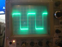
OK no magic smoke it appears to be alive! Currently running an 800mA Bias with 24volt supply and it is producing about 4 Volt peak to peak into an 8ohm dummy load.
This is the waveform at 80KHz there is some strange rounding on the negative slope this is mimicked at the input as it appears to load my 50ohm output signal generator.
.jpg")
I'm also getting an offset of about 0.69 volts and the offset pot will not let me reduce any further possible big miss match between the hockey pucks?
Also the trimmer in parallel with the thermister has a huge effect on both the offset and bias is this normal?
Will not be able to connect it to a speaker until I have resolved this huge offset. Stay tuned.
This is the waveform at 80KHz there is some strange rounding on the negative slope this is mimicked at the input as it appears to load my 50ohm output signal generator.
I'm also getting an offset of about 0.69 volts and the offset pot will not let me reduce any further possible big miss match between the hockey pucks?
Also the trimmer in parallel with the thermister has a huge effect on both the offset and bias is this normal?
Will not be able to connect it to a speaker until I have resolved this huge offset. Stay tuned.
OK update, I keep forgetting these lovely amps are class A and in my excitement to get this up and running must remember to let them get up to temperature before doing any serious tweaking or trying to put music through them.
It is now rock solid pulling 800mA at 24 volts supply 0.2mV offset and the frequency response goes way beyond 250KHz!
Of course we are all here because we want to make a great sounding amp so listening tests will commence when I get a better power supply.
It is now rock solid pulling 800mA at 24 volts supply 0.2mV offset and the frequency response goes way beyond 250KHz!
Of course we are all here because we want to make a great sounding amp so listening tests will commence when I get a better power supply.
Offset is easily fixed by changing a resistor value in bias circuitWill not be able to connect it to a speaker until I have resolved this huge offset. Stay tuned.
Last edited:
Thanks Guys I had the amp on all night to see if the Bias or the Offset drifted and it held steady thanks for the pointers. Now to get a power supply to really listen to it!
Still need to finish off mounting binding posts and iec socket on each monoblock.
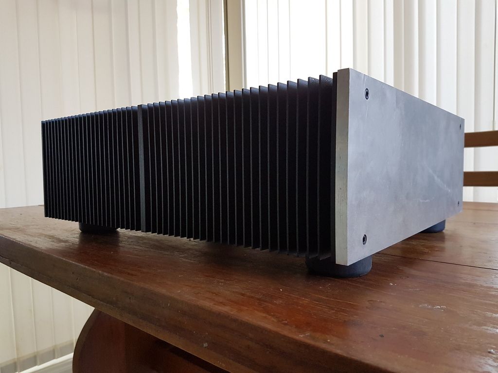
It's looking great 2Pico! Do you have more pics to show us?
Thanks 2 picodumbs. I managed to get a quick test in.
This was just one channel versus the F6 and it certainly sounded a bit brighter but obviously only having zero gain I needed to up the preamp driving it but it had all Pass characteristics we have come to love tight bass and control.
I will add a gain stage in the form of the PMBF4391 and the HA5002 together with a stiffer power supply and get the bias up to somewhere between 1.3 to 2.0A and test again.
My other observation is that these hockey pucks run hotter than the IRFP's and the C3M's for the same bias and supply voltage has this been your finding too?
Possibly you F6 is already k2 dominant 12db over k3 and your pucks amp not.....:--))
Look at the THD spectrum.
Look at the THD spectrum.
That indeed could be.
Unfortunately I do not have the tools yet to measure THD but soon.
Once I have the front end added I will start to make more measurements I will post my findings. 🙂
Unfortunately I do not have the tools yet to measure THD but soon.
Once I have the front end added I will start to make more measurements I will post my findings. 🙂
I don't have Cree C3M, but they should be much cooler than irfp240 etcMy other observation is that these hockey pucks run hotter than the IRFP's and the C3M's for the same bias and supply voltage has this been your finding too?
No I'm not sleeping Mighty ZM. In fact I'm still trying to get the temperature compensation to work a little better.
Some interesting findings though if I sweep the frequency with my function generator the current both positive and negative currents fluctuate massively but together. But the strange thing is the output across my dummy load does not change at all.
Another interesting observation is that this peak of current appears at around 8.5KHz.
I'm currently not able to increase the bias much past 800mA due to my wimpy power supply hope to get one together some time over the weekend. I think Generg is running 2Amps or greater which I suspect the sweet spot is for these devices.
Does this answer or somehow linked to your question linear ratio of Iq vs. PSU rails voltage acceptable?
Interesting journey all the same this is why we are here. Anyway I do indeed have to go to bed I have an Autodesk Inventor course all day tomorrow so need to be in Tip Top shape for that.
sleepin' Dodobeauties .......

Awakened beauty .......question seems to be so diffficult that I prefer to sleep again ....
Augmenting beautiness...
😀
Concerning stability....
at least my "running at home" version with no source resistors at the J-Fets and at the pucks but with 47R at the sources of the SK/SJ
seems to show no oscillation.
10kHz around 4.5V/8 Ohm
I have not much experience in judging rectangles so tell me what you think, please.
😀
at least my "running at home" version with no source resistors at the J-Fets and at the pucks but with 47R at the sources of the SK/SJ
seems to show no oscillation.
10kHz around 4.5V/8 Ohm
I have not much experience in judging rectangles so tell me what you think, please.
😀
Attachments
Well finally got the front end done with the HA5002 buffer with a PMBF 4393 Fet.
.jpg")
Still running wimpy power supply 24 volts at 800mA bias but am able to get the buffer to swing plus minus 20V. So here is the beast at around 15V pp into 8ohm dummy load running at 150KHz really nice square wave. (Starts to round off at around 230KHz but its -3dB point must be somewhere out in the MHz!)
.jpg")
So how does it sound? This is after all what we are all doing here! Using a very crappy speaker used for testing it is very clean with excellent detail.
Thanks to 2 Picodums for the circuit and Generg for the encouragement in getting it done. Now I have to save up for a power supply and a case!
Still running wimpy power supply 24 volts at 800mA bias but am able to get the buffer to swing plus minus 20V. So here is the beast at around 15V pp into 8ohm dummy load running at 150KHz really nice square wave. (Starts to round off at around 230KHz but its -3dB point must be somewhere out in the MHz!)
So how does it sound? This is after all what we are all doing here! Using a very crappy speaker used for testing it is very clean with excellent detail.
Thanks to 2 Picodums for the circuit and Generg for the encouragement in getting it done. Now I have to save up for a power supply and a case!
sleepin' Dodobeauties .......
Ran out of IEC Socket/switch/fuse. Placed an order for some new ones.
- Home
- Amplifiers
- Pass Labs
- F4 Beast Builders