Apparently my version of LTSpice (4.23i) running under Wine does not have cursors. It shows the same information at the bottom left of the LTSpice window.
real confusion.....😡
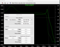
why is the phase value of the box so different from the value shown on the right side?
here is the situation with the Aleph3.....
Sorry Mister Pass all mistakes due to me and Spice......😀
If I take serious what the box says Aleph 3 has no gain margin with neg. dB values, only relative to the gain 20dB itself. Is this already enough?
When I take serious the information on the right bar it is -24dB.
Hu, Hu ...... I feel again at starting point.
Attachments
The magnitude value is correct. The phase value corresponds to the position on the dashed curve (phase) at the frequency determined by the horizontal position of the cursor. In all cases the vertical position of the cursor is irrelevant.
o.k. that means the my Aleph3 Spice clone shows no neg dB value at 180° and should oscillate heavily.....
Correct?
Hope not!
Correct?
Hope not!
I have the impression we search a ghost...
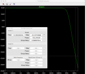
The Sony II version 1 frontend alone fulfills the demands pico told perfect, combined with the Puck output stage all gain margin at -180° is gone.
Is it possible that the models we have for our Pucks do not have the lower capacities starting around 15V and so we get und must get always wrong results?
the Sony II frontend version 1 shows a very good behavior ... if it is allowed without output stage to say anything.
"And Lynn, please what kind of phase shows the vertical bar?"
I do not understand the question.
Is that the Sony-2 with cascode feedback and no global feedback? It does look good.
Last edited:
the phase bar on the right side we switch off...what does it show?
Sony II frontend and CFB and I connected the 750R instead to the OS output to the FE output.
I wanted to isolate the problem.
I think it is not in the frontend making bad values, but possibly our models do it in the OS stage.
Sony II frontend and CFB and I connected the 750R instead to the OS output to the FE output.
I wanted to isolate the problem.
I think it is not in the frontend making bad values, but possibly our models do it in the OS stage.
I have the impression we search a ghost...
The Sony II version 1 frontend alone fulfills the demands pico told perfect, combined with the Puck output stage all gain margin at -180° is gone.
Is it possible that the models we have for our Pucks do not have the lower capacities starting around 15V and so we get und must get always wrong results?
Adding global feedback will change things drastically. In linear circuit analysis, this circuit produce poles or zeros for each capacitor in the feedback loops. Each fet has an associated capacitor, thus there are something like 8 capacitors total contributing to the Bode plot. Very complicated. Adding the output stage adds two capacitors, but also adds additional phase delays to the feedback.
I cannot claim that I really understand how to optimize the design to account for all of the reactive elements.
Seems I got irritated by not switching off the right sidebar...
why are the sidebar values different from the phase degree values in the box.....
....🙂
Actually they are not different but it is easy to make mistakes reading it correctly. that is why I suggest just turning it off.
You just proved my point. 🙂
the Sony II frontend version 1 shows a very good behavior ... if it is allowed without output stage to say anything.
You're just confusing yourself here.
Stick to your chosen circuit and make it work.
I have a script for measuring phase margin and gain margin.
Here are the important statements:
.measure ac F3db when mag(V(out))=MagVout/sqrt(2) fall=1
.measure ac phase_margin find atan(im(V(out))/re(v(out))) when mag(V(out))=1
.measure ac gain_margin find -20*log10(mag(V(out))) when atan(im(V(out))/re(v(out)))=0 fall=1
It is important that you limit the frequency range to above about 20Hz so that some lo-freq rolloff doesn't confuse things.
Read the .measure section of the LTSpice manual.
here is the situation with the Aleph3.....
I highly doubt this.
Either your models are wrong or you have somehow made a mistake with circuit.
I have a script for measuring phase margin and gain margin.
Here are the important statements:
.measure ac F3db when mag(V(out))=MagVout/sqrt(2) fall=1
.measure ac phase_margin find atan(im(V(out))/re(v(out))) when mag(V(out))=1
.measure ac gain_margin find -20*log10(mag(V(out))) when atan(im(V(out))/re(v(out)))=0 fall=1
It is important that you limit the frequency range to above about 20Hz so that some lo-freq rolloff doesn't confuse things.
Read the .measure section of the LTSpice manual.
Nice work Lynn. That speeds up the process
I have some measurement data for the IXFN48N60P.
Is there any reason your transconductance graph for 48N60P doesn't start at the origin 0, 0?
It could, but my measurement jig has limited dynamic range and is only good good down to around 50mA when the max current is 5A or more. I could display the fit results at lower current values, but the higher order polynomials turn to crap outside the range of the measurements.Is there any reason your transconductance graph for 48N60P doesn't start at the origin 0, 0?
I use the remote control features of a Rigol DG1022A waveform generator and a Rigol DS1054A scope. I suppose I should make spot measurements and manually change the scope sensitivity settings to go lower.
Here is an interesting set of view graphs: https://www.ieee.li/pdf/viewgraphs/current_feedback_vs_voltage_feedback_amplifiers.pdf Has anyone seen rhis?
I highly doubt this.
Either your models are wrong or you have somehow made a mistake with circuit.
Not only you....:--))
It shows that it is not always easy to interpret Spice results.
Did anyone notice this in the XA25 Manual?
A simpler way might be to use 2 triple-pole circuit breakers on the transformer secondary windings. The third poles are wired in series and shutdown all power using a latching relay on the mains.
Just guesses.
" Protection: Shutdown at 10 amps output"
I can imagine putting a small resistance sense resistor on the drain of each output FET and having some kind of controller that shuts down the mains power when the AC voltage across any one of the sense resistor is Vsen-pp/Rsen > 10A*2.
A simpler way might be to use 2 triple-pole circuit breakers on the transformer secondary windings. The third poles are wired in series and shutdown all power using a latching relay on the mains.
Just guesses.
Last edited:
- Home
- Amplifiers
- Pass Labs
- F4 Beast Builders