Nice work.Here is a Gm vs. I(d) plot for the 2sk2013. It tracks excellently with the datasheet.
BUT, the bias situation is far from perfect.
At 50mA, Gm=.3 S. The Vgs vs. temperature plot in post #373 has a slope of -1.8mV/C. If the bias current is adjusted for 50mA at an operating temperature 20C above ambient, the bias current will be 1.8mV/C * 20C * .3 S = 10. 8mA lower at the ambient startuptemperature.
I have a stack of different types of small heatsinks, I might test the performance for confirmation of their specs.
In the end though I might just mount them on the main heatsink and bias them to 300mA. Hahaha
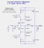
With the cascoded jfets is possible to adjust the H2 magnitude and polarity without using cascode feedback or jfet source resistors. Connecting a resistor from one of the cascode BJT emitters to ground (or rail) will inject a (almost) constant current into emitter, requiring a change to the drian load resistance in order to zero the FE output offset. Changing the drain load resistance also changes the open-loop gain of the jfet stage, thereby changing the H2 balance. Try it.
Attachments
not so fast.....😀😀
I just did your last suggestion!
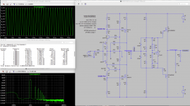
good Spice values and good sound!
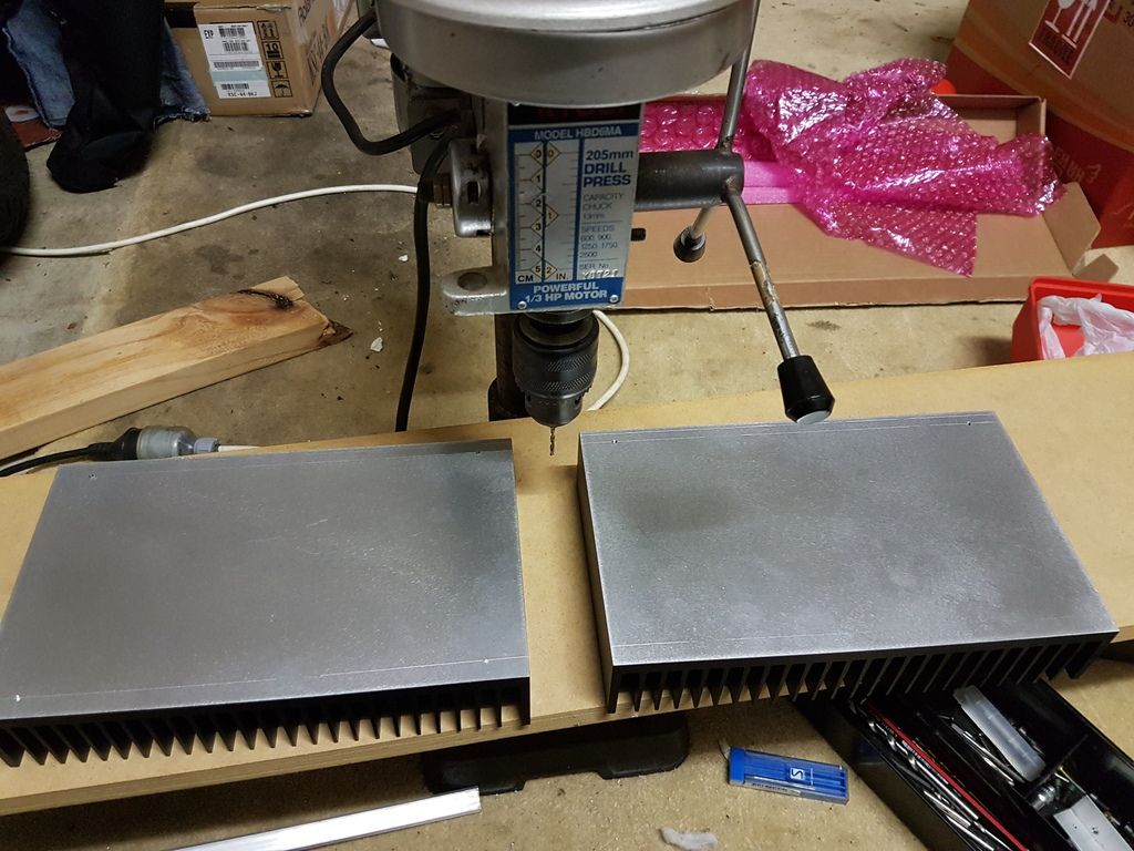
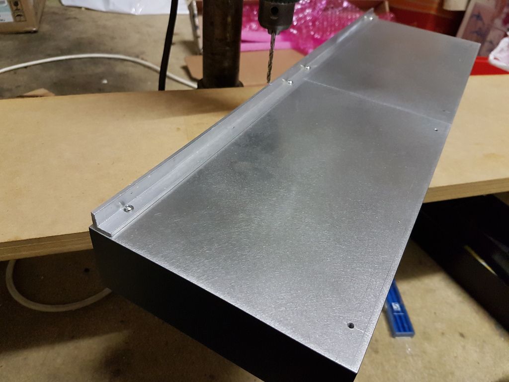
I ordered bigger heatsink for the SK/J not to come in trouble with the possible thermal runaway. In some days I can try to omit the source resistors.
I just did your last suggestion!
good Spice values and good sound!
I ordered bigger heatsink for the SK/J not to come in trouble with the possible thermal runaway. In some days I can try to omit the source resistors.
Attachments
not so fast.....😀😀
I just did your last suggestion!
good Spice values and good sound!
I ordered bigger heatsink for the SK/J not to come in trouble with the possible thermal runaway. In some days I can try to omit the source resistors.
No need to worry. You probably want both negative cascode feedback and some difference in the amount applied to the positive and negative sides.
I was only making a comment about another aspect of cascoded front ends, independent of the use of cascode negative feedback.
Yes I understood of course, it was more a joke ....:--))
Isn't it possible to do the same with an intended "missetting" of the 500 pots at the J-Fets and then adjusting the offset of the front end with the 5k pot in the outputstage?
Isn't it possible to do the same with an intended "missetting" of the 500 pots at the J-Fets and then adjusting the offset of the front end with the 5k pot in the outputstage?
PSRR becomes an issue, unless the ends of the pot are connected stable voltage sources, such as the cascode bias generators driving the bases of the cascode BJTs. Otherwise any hum or noise on the power rails would couple through the feedback network.
The circuit I presented in post #383 also has that problem if the resistors to the rails are used, but is OK with the resistors to ground.
The circuit I presented in post #383 also has that problem if the resistors to the rails are used, but is OK with the resistors to ground.
Yes I understood of course, it was more a joke ....:--))
Isn't it possible to do the same with an intended "missetting" of the 500 pots at the J-Fets and then adjusting the offset of the front end with the 5k pot in the outputstage?
You will also need to check the dc offset at the front end is under 1V otherwise you will lose voltage swing due to clipping at the front end.
I'm not sure if you need that many cat skins to play with when the end result is essentially the same. Just choose a method and build brothers.
You will also need to check the dc offset at the front end is under 1V otherwise you will lose voltage swing due to clipping at the front end.
I'm not sure if you need that many cat skins to play with when the end result is essentially the same. Just choose a method and build brothers.
Most of the fun for me is the change of the circuit to get an impression how the sound is influenced.....!
Most of the fun for me is the change of the circuit to get an impression how the sound is influenced.....!
Yes that is a worthwhile pursuit, I can give you almost endless ideas if you're serious, but Papa's front end circuit is pretty bloody good, I need to build that first before I start trying too many other ideas or I'll go around in circles.
when we take serious the 240W mentioned in the owner manual of the XA25 mustn't the bias for one channel be around 2A?
With +/-25V rails.
Similar to beloved Aleph3.....:--))
With +/-25V rails.
Similar to beloved Aleph3.....:--))
when we take serious the 240W mentioned in the owner manual of the XA25 mustn't the bias for one channel be around 2A?
With +/-25V rails.
Similar to beloved Aleph3.....:--))
That is what I am biasing mine at, hence the reason why all my testing was centred around 2A bias. Plus or minus 10% of that figure would be fine though.
Last edited:
when we take serious the 240W mentioned in the owner manual of the XA25 mustn't the bias for one channel be around 2A?
With +/-25V rails.
Similar to beloved Aleph3.....:--))
What efficiency can be expected from the power supply?
Don't know when brother Generg will be back so here is my 2c.What efficiency can be expected from the power supply?
Without knowing whether CRC is employed and if it is, we don't know the value of R so we can only speculate. Not that, that is the biggest loss, but it all adds up I suppose.
I've never bothered with that sought of calculation too much, a close estimation is probably good enough.
So what do we have
Diode Voltage Drop
IR heating of primary and secondary windings
CRC losses
Is there anything else? Generg will most likely know
I'll probably just go with regular 4 x 0.47 in parallel but I'll be using 528000 uF in capacitance
Last edited:
when we take serious the 240W mentioned in the owner manual of the XA25 mustn't the bias for one channel be around 2A?
With +/-25V rails.
Similar to beloved Aleph3.....:--))
What XA25 Owners Manual? The only power dissipation number I have found is "Idle Power draw: 200 Watts total" in Pass Laboratories XA25.
What XA25 Owners Manual? The only power dissipation number I have found is "Idle Power draw: 200 Watts total" in Pass Laboratories XA25.
At idle the XA25 will draw 240W from the AC Mains.
I'll be kind and leave out the usual "dumb bastard" comment. Hahaha
Attachments
Last edited:
Has anyone looked carefully at the plots in the XA25 User Manual? The THD % scale appears to be off by a factor of 0.1. The plots show 0.01% THD at 50W into 4R, but the written specs say 0.1%. BTW: Where did the User Manual come from? I cannot find it on the Pass Labs site.
- Home
- Amplifiers
- Pass Labs
- F4 Beast Builders