besides what you suggest..... to do.... 🙂)
why do the opto solutions prefer k3?
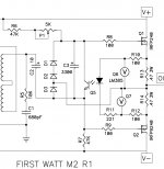
and look at M2, here the gate to gate over the opto exists too....
of course no gain in this stage, is that your concern?
J2 uses the opto too and there is gain in the stage ......but only one gate connected to the opto.
hm, hm.....
why do the opto solutions prefer k3?
and look at M2, here the gate to gate over the opto exists too....
of course no gain in this stage, is that your concern?
J2 uses the opto too and there is gain in the stage ......but only one gate connected to the opto.
hm, hm.....
Attachments
Last edited:
How much negative feedback? Alternatively, what is the open-loop gain?
Open loop gain looks like it is about 50db. Isn't that higher than normal?
no!
🙂)
still your circuit where Toshibas and pucks are buffers and all gain is made by the J-fets?
🙂)
still your circuit where Toshibas and pucks are buffers and all gain is made by the J-fets?
I cannot see how to add a sine of 50Hz to the DC voltage source.....please a help.
In LTSpice you right-click on the Voltage-Source then click on Advanced. The resulting menu will let you choose Sine, amplitude, frequency, ...
Open loop gain looks like it is about 50db. Isn't that higher than normal?
I have been aiming at about 14dB-16dB of global feedback, which means 34dB-36dB open-loop gain (OLG). If you are using cascode feedback (CFB), then you must increase the OLG according to the amount of CFB.
In LTSpice you right-click on the Voltage-Source then click on Advanced. The resulting menu will let you choose Sine, amplitude, frequency, ...
yes I know this, but then I loose my DC 30V source.....
or should I add this Sine voltage source to the DC source .... hu hu
3picodumbs is my name..... 😀😀😀
2picodumbs would know this....
I have been aiming at about 14dB-16dB of global feedback, which means 34dB-36dB open-loop gain (OLG). If you are using cascode feedback (CFB), then you must increase the OLG according to the amount of CFB.
the OLG of 34-36dB includes the loads (1k or less or more or whatever) ?
yes I know this, but then I loose my DC 30V source.....
or should I add this Sine voltage source to the DC source .... hu hu
3picodumbs is my name..... 😀😀😀
2picodumbs would know this....
No, DC-Offset should be set to 30V.
the OLG of 34-36dB includes the loads (1k or less or more or whatever) ?
I measure the open-loop gain by disconnecting the feedback resistor from Output to the feedback network, and disconnecting any cascode-feedback resistors. I measure the global feedback by connecting the cascode-feedback resistors and measuring the gain (without the global feedback resistor). the global feedback is that gain divided by the closed-loop gain.
Almost finished base plates, next up is to drill and tap 100 holes in the heatsinks.
Not looking forward to it.
Hahaha
Not looking forward to it.
Hahaha
Last edited:
still your circuit where Toshibas
Generg, you triggered this thought when you mention the toshibas. I ended up saving to many variations of this circuit. I lost track. Lynn's not going to like this, sorry Lynn but the circuit that I made that had good distortion was with the IRF9610 IRF610. Its the same circuit otherwise with the cascode feedback that you posted.
Generg, you triggered this thought when you mention the toshibas. I ended up saving to many variations of this circuit. I lost track. Lynn's not going to like this, sorry Lynn but the circuit that I made that had good distortion was with the IRF9610 IRF610. Its the same circuit otherwise with the cascode feedback that you posted.
Interesting. A major difference with the IRF9610/IRF610 is that Vgs 250mA with be over 4V, about twice that of the Toshibas. That means that the JFET drain resistances will be about about double for the same feedback network, resulting in about twice the open-loop gain.
Maybe in the original work the FQAs that are also in the Pass HPA
FQP 3N30 and 3P20
FQP 3N30 and 3P20
Last edited:
We already know toshibas are used here, but if all you have is the irf devices then nothing wrong with that.
While trying to understand why I cannot reduce H2 to expected levels, I discovered that the problem is in my front-end circuit. I found a 160MHz oscillation at the emitter of one of the cascodes, which was fixed by adding a 1K resistor between the bias generator and the base of the cascode, like in the Sony-VFET-pt2. But there is another problem I haven't solved where the H2 level and all higher harmonics rapidly shoot up between slightly below 4V peak and 4V peak. This indicates some kind of clipping to me, and is perhaps an oscillation at higher than my 150MHz scope can see.
Since we are no longer using degeneration (another form of feedback) in our front end circuit, the local feedback network will most likely need to compensate for that.
This is a big part of the key to low distortion in this amp, in my opinion.
Might be worth throwing a cap in parallel with your feedback resistor just to start eliminating potential problems.
The output stage is the least of your problems, source follower stages are already inherently low distortion.
You might end up going in a completely different direction again, but it's all part of the fun.
I've got to drill and tap over 100 holes. Why should I be the only one that suffers.
Hahaha
Last edited:
How could you need 100 holes in the heatsinks? I count 2 X (8 + 4 + 4) = 32 for my build. The is 2 heatsinks, each with 8 PCB mounting holes, 4 hocky-puck mounting holes, and 4 holes attaching the heatsinks to the rest of the chassis.
Because I have a secret plan.
Muah hahaha
2 cases, 4 heatsinks, 28 holes per heatsink
If I include the other holes already tapped for case assembly it's 28 + 12 per heat sink.
160 bloody holes drilled and tapped.
The beast of a 1000 bloody holes. Hahaha
Muah hahaha
2 cases, 4 heatsinks, 28 holes per heatsink
If I include the other holes already tapped for case assembly it's 28 + 12 per heat sink.
160 bloody holes drilled and tapped.
The beast of a 1000 bloody holes. Hahaha
Last edited:
- Home
- Amplifiers
- Pass Labs
- F4 Beast Builders