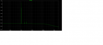
I truncated the number of digits in the polynomial coefficients
Well then I will have to disagree with Picodumbs. Spock would not have done that.
Only when he was under the spell of mating duties back on Vulcan.Well then I will have to disagree with Picodumbs. Spock would not have done that.
Well then I will have to disagree with Picodumbs. Spock would not have done that.
I don't agree with everything Lynn or Spock does, it's the raw data that I appreciate (not the maths).
Thanks to Lynn for his work.
Only when he was under the spell of mating duties back on Vulcan.
Oh yes, your talking about pon farr where Vulcans becomes irrational and cranky every seven years. Yes very sad. Well I don't know but does that fits you Lynn?
I truncated the number of digits in the polynomial coefficients, and it shows for Id < 1A.
I did noticed it right away when I compared it to your data set. I was wondering about that until I read your post.
I see no need pico. I would need to buildup the whole measurement setup and you and Lynn and Rob do a very good job.
I occupy with the optocoupler variant shown by pr. I hope to have an experimental setup soon.
I occupy with the optocoupler variant shown by pr. I hope to have an experimental setup soon.
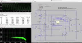
The basic idea of what the circuit might look like was done a while ago now. I have the circuit done in ltspice that I want to build and it looks pretty much the same as Lynn's circuit. It's just a matter of building and tweaking I don't have time to build it now though. With the right selection of cascode resistors, gate resistors and second stage output resistor the second harmonic is nearly eliminated at 1 watt output. Second stage bias is at 58ma.The bandwidth is at about 200khz.If the built circuits distortion is a tenth as good as the simulated circuit then it will be good.
Attachments

Last edited:
With the right selection of cascode resistors, gate resistors and second stage output resistor the second harmonic is nearly eliminated at 1 watt output.
Do you like the sound of dominant third harmonic? I thought most of us were searching for low overall THD (<.01%) with dominant (negative phase) second harmonic.
I like dominant 2nd harmonic. I just wanted to see how low I could get the distortion. Now I simulated it with cascoded pucks and it dropped even lower. I doubt that I can get that low in the real world but I hope that the lower it is in the simulation the chances are it is pretty low in the real world and worth building. Picodumbs and Lynn could maybe make some more accurate models, I don't have the knowledge to do that yet.
If you want to control amplifier harmonic character, you must also to control loudspeaker complex impedance.
It is interesting how the Pass labs doing that, it's explained in their
loudspeaker owner manual.
https://passlabs.com/sites/default/files/SR-1_om.pdf
It is interesting how the Pass labs doing that, it's explained in their
loudspeaker owner manual.
https://passlabs.com/sites/default/files/SR-1_om.pdf
I like dominant 2nd harmonic. I just wanted to see how low I could get the distortion. Now I simulated it with cascoded pucks and it dropped even lower. I doubt that I can get that low in the real world but I hope that the lower it is in the simulation the chances are it is pretty low in the real world and worth building. Picodumbs and Lynn could maybe make some more accurate models, I don't have the knowledge to do that yet.
I am having a hard time nulling the 2nd harmonic. My measurements of the IXYS output fets indicates a good match of transconductance, but when the shapes of the Id vs. Vgs curves is carefully analyzed the 2nd harmonic of the undegenerated push-pull output stage, without feedback, has a fairly strong 2nd harmonic. When feedback is introduced, the phase delays appear to make it difficult to null the 2nd harmonic by tweaking the front-end. Perhaps I am missing something, but that is what I am seeing in both simulations and bench measurements. Perhaps my chioce of output fets (IXTN40P50P and IXFN48N60P) is not the best.
After reading your last post I realized I uploaded the wrong pic when I went back and edited it. I got discombobulated again. I didn't get the 2nd harmonic nulled completely until I cascoded the pucks. I didn't even notice I was working with that version of the circuit. The only difference in the circuits are the two extra pucks. I'm using the IXFK44N80Q3 in the simulation and I am only doing simulations at this time.
The bandwidth on mine is the same as the xa25 at 200khz, what is yours at Lynn?
The bandwidth on mine is the same as the xa25 at 200khz, what is yours at Lynn?
Attachments

Those distortion plots look excellent. What is the frequency and power level? My bandwidth from input to output is around 140kHz, and the feedback loop bandwidth is around 800kHz.
I'm looking at your data. Too many bloody data points. Hahaha
Can you minimise the data points or reformat the data so I can import into excel with out the brackets.
If you can fix it up, I'll have a go at making a model to match your data.
Can you minimise the data points or reformat the data so I can import into excel with out the brackets.
If you can fix it up, I'll have a go at making a model to match your data.
I'm looking at your data. Too many bloody data points. Hahaha
Can you minimise the data points or reformat the data so I can import into excel with out the brackets.
If you can fix it up, I'll have a go at making a model to match your data.
That is why I did the polynomial fits. You can generate the number of points to desire using the polynomials. Alternatively you could apply a 3rd or higher order smoothing filter to the raw data and subsample the results. Do you have MatLab or GNU Octave?
😀The circuits with the "normal" thermistor bias solution à la F4 seem all to be k2 dominant.
PR´s OPTO solution and RobLK solution with opto also, behave all more like PP stages. K2 is cancelled and k3 dominant.
I conclude that the thermistor bias solution makes the k2 effect!
(keen, and may be wrong!)
any other explanation?
😀
PR´s OPTO solution and RobLK solution with opto also, behave all more like PP stages. K2 is cancelled and k3 dominant.
I conclude that the thermistor bias solution makes the k2 effect!
(keen, and may be wrong!)
any other explanation?
😀
Attachments
😀The circuits with the "normal" thermistor bias solution à la F4 seem all to be k2 dominant.
PR´s OPTO solution and RobLK solution with opto also, behave all more like PP stages. K2 is cancelled and k3 dominant.
I conclude that the thermistor bias solution makes the k2 effect!
(keen, and may be wrong!)
any other explanation?
😀
Do you have and estimate of the PSRR with the opto bias circuits. My concern is with the gate-to-gate connection or the opto circuit. You can test this by modifying the rail Voltage sources to have a 60Hz (or 50Hz) sine component and enabling the AC Amplitude of the voltage sources. Run AC Analysis and you will see how the sine component on the rails affects the outputs. I am also concerned about the need for higher rail voltages to allow full 25W output.
- Home
- Amplifiers
- Pass Labs
- F4 Beast Builders