The only problem when you do it like that is the 0V is not at ground potential due to the CRC on the negative rail.
I haven't gotten the PCB yet, but from pictures it looks like I could use it either way. Since dual-mono might have a positive impact on SQ I'll probably go that way if it looks doable. (Dropping out half the CRC to get the negative rail to ground will mess with my OCD. 😉 )
I'm fairly sure I have this right, but if I switch to dual-mono, then I need to double the voltage of the capacitors, but I can halve their capacitance. So 50V or 63V 8200uF. Yes?
Get the biggest value caps you can fit.
You're limited to 35mm in diameter using the diyaudio store pcb.
The onboard cap multiplier does most of the filtering but I always go for the biggest that will fit. Sooner or later you might decide to build something else which might require bigger value uF caps.
You could also consider screw terminal caps and forget the pcb, united chemicon U36D or U32D are good value for screw terminal caps.
Last edited:
P1 & P2: single turn, or multi-turn? (It looks like the production units have single-turn?)
Thanks,
Jeff.
Thanks,
Jeff.
Didn't the fetzilla have a tricky bit of filtering on the 0V line?
Appreciate that was a bipolar supply in total, but I do recall a CRC setup on the zero volts point...
Appreciate that was a bipolar supply in total, but I do recall a CRC setup on the zero volts point...
Both the Bourns 3386P (single-turn) and PV12P (4-turn) have the correct pinout spacing. If the circuit isn't hyper-sensitive, then it seems like the single-turn would be easier....
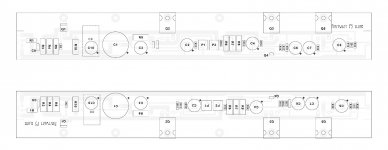
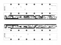
Updated version of my boards. I think I'm about ready to try etching them, but I've got a couple of simpler projects lined up to experiment with first.
A couple of notes: I've posted low-res versions to save bandwidth. If anyone else want to try them, message me and I'll send you 600 dpi versions. Keep in mind though that these are simple graphic files suitable for toner-transfer home etching. They are not Gerbers. (I grew up in the days of tape and mylar, and you know the saying about old dogs and new tricks.)
A couple of notes: I've posted low-res versions to save bandwidth. If anyone else want to try them, message me and I'll send you 600 dpi versions. Keep in mind though that these are simple graphic files suitable for toner-transfer home etching. They are not Gerbers. (I grew up in the days of tape and mylar, and you know the saying about old dogs and new tricks.)
Attachments
A question on the circuit:
D1 is there solely to protect Q5's gate from excess voltage as C5 discharges if the power supply is discharged faster. Is that correct? (In which case a 1N4007 will also work.)
Thanks,
Jeff.
PS: while I do have some 1N4007s on hand which prompted this question, it's really more about me starting to understand these circuits than about saving the $0.25 a couple of 1N4001s would cost me. 😉
PS: while I do have some 1N4007s on hand which prompted this question, it's really more about me starting to understand these circuits than about saving the $0.25 a couple of 1N4001s would cost me. 😉
The 1N4001 has a much lower reverse voltage, but I don't see that, that serves any useful purpose in this location.
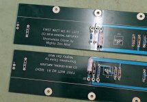
I ended up making a few changes to the coupling cap arrangement (2 x 8,200uF electrolytics and 1 x 8.2uF polypropylene "jelly roll"), and added a bypass (10uF polyester) to C7. My PSU is also a bit different with 36V secondaries and dual mono construction. So I don't think "clone" really fits anymore.
I thought about "DIY F3", but I'm also trying to capture the aesthetic of the Firstwatt production units, and DIY doesn't suggest that to me.
How about:

?
I thought about "DIY F3", but I'm also trying to capture the aesthetic of the Firstwatt production units, and DIY doesn't suggest that to me.
How about:
?
Attachments

think Jazz standards
whatever you do , name of the song is there , same as author(s)
DIY doesn't need to be pejorative (of lesser quality) .... it simply means not made in series , when quality is there
whatever you do , name of the song is there , same as author(s)
DIY doesn't need to be pejorative (of lesser quality) .... it simply means not made in series , when quality is there
I didn't mean DIY as pejorative. Rather to me it conveys a custom implementation, not just a non-series implementation. Sort of like doing a cover song, but as yourself.
Whereas I'm (shamelessly) copying the form-factor of the production implementation as well. More like doing a cover song dressed up as the original act. Which led me to "tribute act".
Cheers,
Jeff.
Whereas I'm (shamelessly) copying the form-factor of the production implementation as well. More like doing a cover song dressed up as the original act. Which led me to "tribute act".
Cheers,
Jeff.

- Home
- Amplifiers
- Pass Labs
- F3 Builders Thread