A couple of questions on the feedback circuit:
1) I presume R2 sets the amount of feedback (6dB)?
2) What is the purpose of C9 across R2?
3) What type of capacitor will work best here? (It appears the production unit uses a mica cap?)
Thanks,
Jeff.
1) I presume R2 sets the amount of feedback (6dB)?
2) What is the purpose of C9 across R2?
3) What type of capacitor will work best here? (It appears the production unit uses a mica cap?)
Thanks,
Jeff.
R2 in combination with R1 sets the input resistance of the amp at ~ 50k . The purpose of C6 and R1 is to shield the amp from extremely high frequencies, frequencies well above the audio band.
A couple of questions on the feedback circuit:
1) I presume R2 sets the amount of feedback (6dB)?
2) What is the purpose of C9 across R2?
3) What type of capacitor will work best here? (It appears the production unit uses a mica cap?)
Thanks,
Jeff.
1)yes with maybe R1 in the mix as well
2) improves square wave response.
3) I always prefer a film cap
Ahh... good find, Dennis.
But this begs the question: in many pictures of F3s (including the production units), it appears that a mica cap is used here. The micas I've found in this size are more expensive than film, so I don't think it's cost savings. Is mica better for this particular application?
FWIW, Charcroft markets their silver mica caps as "ideal for low value capacitors in RIAA or feedback circuits". (But hey, marketers will say almost anything, and most iRIAA filters I see use films, so go figure.)
Converting dual-rail PS to single-rail
OK, perhaps a stupid question, but:
If I'm using the "standard" dual-rail FirstWatt PS for an F3, then I want to convert to single-rail by joining the grounds of the two sections together so that I have 46V between +23 and -23.
Do I let this center section float and tie the -23V to chassis ground and left/right channel ground?
... or do I tie the center section to chassis ground (as in the dual-rail schematics) and let the -23V/left/right channel ground float?
Thanks,
Jeff
The -23V RAIL now becomes 0V.
Then the +23V RAIL now becomes +46V.
Do not install CRC resistors on the old negative volt rail (now 0V) just add links.
There is also another way to do it but it would depend on pcb design.
Then the +23V RAIL now becomes +46V.
Do not install CRC resistors on the old negative volt rail (now 0V) just add links.
There is also another way to do it but it would depend on pcb design.
Last edited:
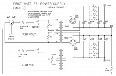
R5 to R8 is zero Ohms.
Get rid of the thermistor link.
You only use one bridge rectifier
Look at the Delite article to see example of correct implementation.
Get rid of the thermistor link.
You only use one bridge rectifier
Look at the Delite article to see example of correct implementation.
More importantly what pcb are you using?
If you have 50V caps you could wire it up for dual mono operation.
It really depends on the pcb layout.
If you have 50V caps you could wire it up for dual mono operation.
It really depends on the pcb layout.
R5 to R8 is zero Ohms.
Ooops; copied the wrong schematic. The other one I have is numbered backwards from that one.
Get rid of the thermistor link.
You only use one bridge rectifier
Look at the Delite article to see example of correct implementation.
Hmmmm... in that case it might make sense to go to a single set of 50V or 63V capacitors as well.
I'll have a look at the other article.
Thanks again!
Jeff.
He he... looks like we cross-posted.
I'm planning on using the "jims_audio" boards (although I got mine for "best-for-sell" as jims_audio was on vacation when I ordered).
I'm planning on using the "jims_audio" boards (although I got mine for "best-for-sell" as jims_audio was on vacation when I ordered).
If the pcb 0V is not linked together like diyaudio store pcb you could wire it up for dual mono operation.
Either one transformer with dual 36V secondaries or two transformers with dual 18V secondaries wired together in series.
Either one transformer with dual 36V secondaries or two transformers with dual 18V secondaries wired together in series.
Thats an excellent idea as it might even improve the SQ.
I can get a 2x35V tranny for the same price as the 2x18V I was looking at. I presume the 35V vs. 36V won't make and appreciable difference?
I can get a 2x35V tranny for the same price as the 2x18V I was looking at. I presume the 35V vs. 36V won't make and appreciable difference?
So just to be clear, the center section (the two grounds of the dual-rail supply) are left floating, and the -23V rail becomes the chassis ground (as well as the ground for the left and right channel boards). Yes?
And R1 - R4 should be 0ohms (i.e.: wire)?
In the schematic if you measure between V- and V+ with a voltmeter you will see you have approximately 50V without a load. The V- becomes ground. No changes necessary. Same 18V transformer and PS section for most Firstwatt builds can be used. The amp boards are just hooked up differently.
- Home
- Amplifiers
- Pass Labs
- F3 Builders Thread