Sorry ZM, Greetings to you, too - it's been a while ....
The 845 - it's a 'beefed up' Music Angel 845 - nothing really special in your league but quite a good 'bang for the buck' cheaper china package - it does mate up fairly well with the Coral beta8 drivers and the passive Xovers and is quite 'musical' with a good sense of rhythm to it - there are some limitations, naturally enough ...
If you could remember, what was the power output of that Balanced F3 amp of yours back then? I think it put out more than 1.5A, yes?
If it's of interest, the factory version (First Watt F3) gets to about 45*C at about room temp 28*C - my 'clone got 'upped' a bit and runs a bit higher current and I found it sounded slightly better at about 55*C on the sinks - used those Thermo isolation pads so the transistors were only a couple of degrees hotter t(han using mica & goop) until mid summer and they got to about 65*C plus -
I imagined they sounded better but I did same thing with small fan and cooled it down a bit 'just in case'
There's just something 'right' about the sound of this amp,IMO ....
I'd agree, it does perhaps sound slightly more detialed if I let it run at 65c, just didn't want to cripple the life span too much. As soon as I find larger heat sinks I'll make a new case. Compared to my ASL AQ-1006 845 DT's with good tubes it's different and better in some ways, not in others so they both have to stay now. The 845 is more detailed in the mid and higher frequencies but the F3 has a little fuller midrange sound, makes tighter bass which could be due to component synergy, speakers etc. Both are really enjoyable and if you compare the cost between the 2 it's no contest dollar per enjoyment factor ratio.
Last edited:
I just fired up my F3 and one channel sounds fine but the other is motor boating but only when a signal is applied. I have not done any testing yet but I was curious if anyone else has seen this happen. Opinions and advice always welcome. It will this afternoon or tomorrow before I see if I can find the problem.
you know the drill ...... pictures
You are correct, I know the drill. I am going to do some checking later today or tomorrow. A good chance to try out my new digital scope. If I do not succeed I will post pictures and cry louder. I did install some leads on the LU1014's where they could be off the heatsink enough and I am suspicious of the extra wire length. A little strange it only happens when a signal is applied. First time to experience this. The boards are from Ebay.
I am just hoping for "I had the same thing happen and I did this and that and cured the problem."
Last edited:
I often wonder....
How do you notice motor boating? Is it measurable? Is the offset going wild or the bias of the amp moving up and down? Is it hearable? Low frequency moving of your bass speaker?
How do you notice motor boating? Is it measurable? Is the offset going wild or the bias of the amp moving up and down? Is it hearable? Low frequency moving of your bass speaker?
Update, no pictures because I cannot see where it would help being this is not my first build and I have done extensive testing and observation with glass. After pulling all the parts and checking each one of them and I found they are correct in the right holes. I then traced all the parts and I did find that the P1 and P2 pots are not wired per the schematic and I thought that was the problem but the other channel is working. I corrected the board where it is exactly like the schematic with no change. I still have .5V at the grid of Q1 whereas the working board has a few millivolts. Also I have the same .5V on the output + and -. I decided to pull Q1 the LU1014 and see if the .5V was still there. It is not with Q1 out of the circuit. My thoughts are bad Q1. I do not have a 3V 1 amp power source to check the LU1014 but I have ordered some more LU1014's. The boards are from Ebay but I am not going to reveal the source publically for personal reasons. I could build the simple circuits on a proto board which may be the choice I may have to take.
I have both channels playing now without motorboating. I still have .5V on both speaker outputs but this measuring from ground not between the terminals. The dc offset is negligible, a few millivolts, when measuring between the output terminals. I decided to just hook it up on some test speakers and see what happens. Viola it plays. I still need to do some biasing by changing R5 but at least now I have it playing without motorboating. Changing the board traces at P1 & P2 to match NP schematic seems to have cured the motorboating. I should have traced out the board before building. It would have saved a lot of trouble.
I am enjoying the F3 so much with my horns I decided to build the Zen 8 to see how a less part F3 would sound. Sometime listening just to the transistor can be satisfying so I have built the Zen 8. I cannot find a dedicated Zen 8 thread so I am posting here. Too much noise using my horns for dedicated use but a very satisfying sound. I cannot compare the differences between the Zen 8 and F3 because both use the same test case.
Is there any reason I cannot add the Q4 noise reducing circuit of the Zen 9 into this resistance current source amplifier? I am going to give it a try and see what the results are unless someone says not to. Figure #2
http://www.firstwatt.com/pdf/art_zv9.pdf
Is there any reason I cannot add the Q4 noise reducing circuit of the Zen 9 into this resistance current source amplifier? I am going to give it a try and see what the results are unless someone says not to. Figure #2
http://www.firstwatt.com/pdf/art_zv9.pdf
Attachments
You can add a cap multiplier power supply to most things.
Make sure you include R8, C3, D1.
R9 is just your standard gate stopper.
Make sure you include R8, C3, D1.
R9 is just your standard gate stopper.
You can add a cap multiplier power supply to most things.
Make sure you include R8, C3, D1.
R9 is just your standard gate stopper.
Many thanks.
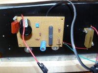
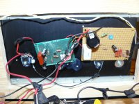
I tried to install the cap multiplier noise reduction circuit in the Zen 8 build and my Antek 400VA transformer that had a slight amount of buzz grew much worse and this was with just one channel hooked up. Instead I decided to just delete and add parts to my board to build the Zen 9 which was my plan to begin with. I built the Aleph current source on a separate board and the cap multiplier is just built pp. This is my test box with heatsinks and PS I use to try my projects. I understand this is the F3 builders thread but the F3, Zen 8 and Zen 9 are interconnected and I decided to post here. I admit to being just a solder slinger and this is just a test amplifier and not intended to be used as a dedicated amplifier. Built only to play with different amplifiers so excuse the messy build but it runs and sounds fantastic with my horns. It was not without problems. Building on proboards give me the most trouble because after determining where the part should go and flipping the board everything is in reverse but I love the challenge and this kind of build is more satisfying for a solder slinger than a ready to stuff board. I admit to 2 days of running down errors in both channels but it now works. I have not scoped the build yet but I should find time today to do so. The placement of the boards was determined on where I already had holes drilled and tapped. Lazy
Attachments
Last edited:
I understand this is the F3 builders thread but the F3, Zen 8 and Zen 9 are interconnected and I decided to post here.
No problem with that.
Keep updating.
Pictures are good too.
I have been enjoying this build tremendously with my horns. I did take the time to scope this build and was surprised at the good looking square waves I saw, better than some ready to stuff board builds. This build is like many of my lady friends of past years, not very pretty but sweet. At least at first. With horns single ended amplifiers just sound so natural and sweet.
Since there is such interest after all these years, I am posting some pdf
documents that you will find useful.
The LU1014D you probably have already, as well as the F3 owner's manual
which is also found at FIRST WATT - in particular, the performance curves
of a production unit.
The full schematic of an F3 channel you might not have, so here it is also.
Not previously seen is the measurement information for selecting the Jfets
and the data on a sampling of the actual parts tested for this amplifier,
along with the calibration curve for minimum distortion via choice of R5
against the Vgs results of the selection test.
Thanks to Papa
Attachments
I'm just starting a DIY version of the F3, and trying to keep close to the internal aesthetics of the production version. There's something about the horizontal, long & skinny boards that really appeals to me.
Since I'll be using the toner-transfer method for my PCBs, I'll have no through-plated holes. While that doesn't necessitate a single-layer design, it certainly encourages it. With that in mind, I've done a layout of the right channel on a single layer. I thought I'd post it here before doing the left in case there's any feedback about doing something different.
Cheers,
Jeff.
Attachments

Last edited:
- Home
- Amplifiers
- Pass Labs
- F3 Builders Thread