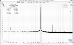
Here's a plot from REW of the right channel. 950Hz at 1W into an 8R resistor. I was rather pleased. I twiddled P2 a little to lower higher order harmonics rather than minimize THD, which at 0.018% isn't outrageously impressive, but is certainly acceptable, given that it's almost all H2.
Like I've reported elsewhere here, I find using measuring this way very "twitchy", in that results seem to depend a lot on positioning. This was done with the amp in the middle of the floor, the Focusrite a couple of feet from it, both four feet or so from the power supply, and the flourescent lights downstairs off. Changing position (or turning the lights on downstairs) affects the noise floor, so I picked the arrangement that gave the clearest measurements.
Nigel
Attachments
Sorry to bring this thread up but I got difficulty at LU1014D measurements.
Hooked them up according to the known schematic, put 3V/1A on bench power supply. Source Resistor 1R 3W. When I power up, none of my 6 (definitely genuine) LU's is getting a VGS >1V. I got 3 at 0,93 and the others below... where is my failure? Crocodile clip 1 is on source side resistor, measuring against ground (which is connected according to circuit do gate).
If I follow the table, ideal R5 would bei somewhat around 1.8R, right?
Can you confirm the test setup schematic and pinout?
Edit: You're not current limiting the PSU output, are you? In the Vgs test, you're supposed to supply 3V and let the current settle wherever it's at. Just to be sure, confirm 3V from Ground to Drain with a DMM.
Last edited:
I did Rodeodave. 3V goes from Power supply to Pin2. Pin1 is connected to PSU -. Pin 3 is connected to 1R Resistor which is connected to PSU - as well. I measure VGS on Source and on common -.
At 3V the LU is getting warm rather quickly and VGS rises. But from my understanding, it should be measured at Room T.
At 3V the LU is getting warm rather quickly and VGS rises. But from my understanding, it should be measured at Room T.
Your test setup sounds good.
I would have thought that it's supposed to be measured under in-circuit conditions, but the article clearly states the following: "Using a 3 volt supply capable of greater than an amp, measure the Vgs of the device while the transistor case is still near room temperature. Most of them will sit between 1.0 and 1.1 volts, and you can use the graph to estimate the best value of R3 usually between 1 and 3 ohms."
If you have a 5R potentiometer and distortion analyzer, you can determine the resistor's value in situ by minimizing the distortion.
Sadly no distortion analyzer at hand at the moment. At 3V my bench supply sais a current load of about 0.69-0.7 A. Is this brhavior normal?
Something doesn't add up. According to Ohm's law, U=R*I
So with a 1R resistor, the voltage measured over said resistor directly corresponds to the current (you'll measure 1V per 1A though 1R).
Unless verified, I wouldn't put too much trust into the voltage/current measurements as reported by the built-in meters in a benchtop PSU. I would verify that the PSU output voltage is indeed 3.00V with a separate DMM. If you're running into a current limit, the output will read less and will obviously not reach 3V.
And I'd clamp the LU to a heatsink or a block of aluminum to keep the temperature somewhat constant.
Ok. I measured all again, inbetween a heatsink sandwhich of about 3kg 😂
Behavioral was more stable cause heat was adequatly dissipated. Got 2 that measure around 0.97V stable, The others lower. So best to take those two and add around 1R8 for R5 then?
Behavioral was more stable cause heat was adequatly dissipated. Got 2 that measure around 0.97V stable, The others lower. So best to take those two and add around 1R8 for R5 then?
Wouldn't a Vgs of 0.97V call for an R5 (if you're referring to the F3 R0 11/04/05 schematic, otherwise R3 for Zen V9) of about 1.1 to 1.2 Ohm?


- Home
- Amplifiers
- Pass Labs
- F3 Builders Thread