No, I think that's a dead Q5. I'm just wondering how it got that way. If the diode were in backwards then the discharge of C5 could fry the gate oxide of Q5.
Diode not in backwards, as the amp worked for a few years. However, a drip of water did get in - that could have killed the diode and/or q5.
I'll source replacements for both components.
I'll source replacements for both components.
Success!
I replaced q5 (the diode was fine), and now it powers up normally!
Now I just need to reassemble this heavy lump of metal.
I replaced q5 (the diode was fine), and now it powers up normally!
Now I just need to reassemble this heavy lump of metal.
This one still has my curiosity piqued. The diode is good, so the gate didn't see reverse bias. (The water could have shorted something, but it would have had to have "unshorted" the diode to produce reverse bias.)
Shorting the gate to the drain could produce zero bias, but not reverse bias.
Shorting the gate to the source would over-bias the gate, but the water would have to have much less resistance than the gate stopper to produce destructive over-bias.
Tap water on a circuit board is going to be something like 20ohms to 2Kohms. Salt water (or something like Gatorade) would seriously reduce that though....
Anyway, well done for sorting it!
What if I told you, at the time, it was a 40 degree day, and it may have been a drop of sweat ...
Well, that would be salty all right.
Still, I envy you for even having 40º days. Heck, I'd give my eye teeth for some 30º days....
Still, I envy you for even having 40º days. Heck, I'd give my eye teeth for some 30º days....
F3 transfo
Hi Jeff,
Is my understanding correct that I have to use one 300va transfo, 2 x sec. 36 Volt with the double rectifier in the Carsten set?
Thank you.
Hi Jeff,
Is my understanding correct that I have to use one 300va transfo, 2 x sec. 36 Volt with the double rectifier in the Carsten set?
Thank you.
Good evening,
is it safe to try running F3 with 51V rail voltage just to check if I assembled it correctly?
is it safe to try running F3 with 51V rail voltage just to check if I assembled it correctly?
Ok gentlemen, I am at loss here. Me and my friend have got Jeff Young's PCBs from the recent forum group buy. After yesterdays test, both amps have similar problems and are not working properly in a similar fashion.
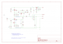
With 51V PSU, I get following voltages (all measurement relative to the PSU ground, is that ok?):
Misc:
PSU ground to Signal ground 44V
PSU+ to Signal ground 5.5V
The amps draw barely any current, Fets don't even get warm.
In the past I managed to succesfuly build a breadboard ACA and kit M2X without much problem, I really wasn not expecting so much problem with F3 😕.
Thanks,
Andy
With 51V PSU, I get following voltages (all measurement relative to the PSU ground, is that ok?):
- Q5 source 48V
- Q2 source 46V
- Q4 C/B/E 48V/46V/46V
- C1 46V
Misc:
PSU ground to Signal ground 44V
PSU+ to Signal ground 5.5V
The amps draw barely any current, Fets don't even get warm.
In the past I managed to succesfuly build a breadboard ACA and kit M2X without much problem, I really wasn not expecting so much problem with F3 😕.
Thanks,
Andy
Attachments
Last edited:
- Home
- Amplifiers
- Pass Labs
- F3 Builders Thread