OK, so there are 2 300va transformers, with 66000uf per channel (in a clc setup). There's a 3a fuse at the mains, and each transformer gets 1.25a. Each channel has a thermistor to safety ground.
This configuration worked for ages.
Again, works fine with the bench supply, except one channel starts with a current spike. Haven't retested the real psu yet - wouldn't mind getting to the bottom of this spike (if it is a problem).
This configuration worked for ages.
Again, works fine with the bench supply, except one channel starts with a current spike. Haven't retested the real psu yet - wouldn't mind getting to the bottom of this spike (if it is a problem).
So no thermistors across the transformer primary windings? I'd say the current surge is expected then -- it's the other one that's a bit of a head-scratcher.
I'll check that.
Which components make up the capacitor multiplier? What should I look for?
On visual, there are no bulging caps, so could it be a transistor in the multiplier circuit?
Which components make up the capacitor multiplier? What should I look for?
On visual, there are no bulging caps, so could it be a transistor in the multiplier circuit?
I'll check that.
Which components make up the capacitor multiplier? What should I look for?
On visual, there are no bulging caps, so could it be a transistor in the multiplier circuit?
If you post a copy of your circuit diagram I will list the part numbers.
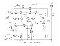
Looking at that circuit, it seems a failure of Q5, C5, or D1 will still result in a functional amp. I'll do some measurements when I get a chance.
Yes it will be functional but could be the cause of the current spike.
R19/C5 would normally provide a soft start up.
If either of those parts are poorly soldered or faulty, then it will prevent the soft start up.
R19/C5 would normally provide a soft start up.
If either of those parts are poorly soldered or faulty, then it will prevent the soft start up.
Well I'm at a loss. I resoldered all the parts that made up the soft start, and still I get the current spike on startup.
Not sure what else to do.
Even the capacitor is measuring fine, so nothing wrong there 🙁
Did some quick voltage checks, and both channels measure similarly too...
Not sure what else to do.
Even the capacitor is measuring fine, so nothing wrong there 🙁
Did some quick voltage checks, and both channels measure similarly too...
which means DC points are pretty much the same on both channels , or you meant that (now) both channels are showing same startup current spike ?
Sorry!
I meant, even though both channels measure the same, only one channel has the current surge.
Think about attaching a small, sacrificial speaker to it, see if the current surge manifests on the output.
But short of rebuilding the channel from scratch ($$$), not sure what else to try...
I meant, even though both channels measure the same, only one channel has the current surge.
Think about attaching a small, sacrificial speaker to it, see if the current surge manifests on the output.
But short of rebuilding the channel from scratch ($$$), not sure what else to try...
So...
Attaching the suspect channel to a sacrificial speaker was fine.
No explosive pops on power up, and a test signal played just fine.
I guess I'll run the amp normally with just a larger fuse, with the intent of one day rebuilding that channel (have a spare pcb).
Attaching the suspect channel to a sacrificial speaker was fine.
No explosive pops on power up, and a test signal played just fine.
I guess I'll run the amp normally with just a larger fuse, with the intent of one day rebuilding that channel (have a spare pcb).
Quick rewind!
When I resoldered everything, I noticed that pad of the middle pin of Q5 was lifted, meaning that Q5 may not have been soldered in correctly (the drain I think? directly attached to V+?).
Don't want to redo everything, so might just run a wire from the drain of Q5 to V+.
When I resoldered everything, I noticed that pad of the middle pin of Q5 was lifted, meaning that Q5 may not have been soldered in correctly (the drain I think? directly attached to V+?).
Don't want to redo everything, so might just run a wire from the drain of Q5 to V+.
OK...
And sorry in advance for all the posts!
But replaced c5, and no change.
I checked voltages again, and the source on q5 is 43.5V, rather than 41V. Is this a sign of a busted transistor?
If so, where can I get an irfp240?
And sorry in advance for all the posts!
But replaced c5, and no change.
I checked voltages again, and the source on q5 is 43.5V, rather than 41V. Is this a sign of a busted transistor?
If so, where can I get an irfp240?
- Home
- Amplifiers
- Pass Labs
- F3 Builders Thread