One channel on my F3 is warmer than the other,so I guess it´s time to adjust the bias.But I lost the instruktion but I have the schema.And I guess it´s P1 I should adjust,but where to messaure and how much..?
Anyone got the instruktions?
Anyone got the instruktions?
The schematic indicates the bias should be 1.1V between R5 and ground. (You could also measure between R3 or R4 and ground.) I believe a CW turn will increase the voltage and a CCW turn will decrease the voltage.
I assume the Cct diag is the "R0 11/04/05" from ther First Watt site
- P1 sets the gate voltage on the cascode Q2 and is around 8volts and should give you that 1.1V that dcrg mentioned - shouldn't move out of adjustment unless temp causing component failure of P1, C2 or one of those R3,4,5
- another one to check is the 0.65V across the power resistors R6,7 and 8 which should also be about 21volts above gnd - if you haven't burnt out a resistor or a solder joint gone bad, should start looking for a cap that's failing
- P2 adjusts the amount of signal is sent to the current source Q3 but this shouldn't effect the temp on the heatsinks if amp isn't passing signal, ie just sitting there cooking!
- hope this helps ....
Question About 15 Parallel Silmic II
If you parallel 15 of the Elna caps together, is there a need for the 220mF and 1mF by-pass caps? Wouldn't the by-pass caps just cloud things up?
Btw- I'm looking at building the Zen 9, it has a 10mF cap and looks to have a different function at the output. Any recommendation on the quality of the C7 10mF cap?
Thanks,
Vince
Last edited:
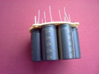
15x 1000uF Elna capacitor
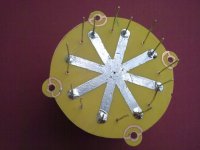
Finally after several months I've rebuilt my Zen v9 into F3 amp. Following the Nelson advice I put (15x 1000uF +220uF) Elna Simic + 1uF propylene capacitor together at the ouput. Connected them into two layer star like pattern (see my previous posts). My Zen9 had 10000uF „Hi sound” Nichicon+10uF propylene. This time I was very careful in choosing transistors and resistors for both chanels more than previously also. Particulary in case of source resististors of JFET Q1. The rest electro caps are Nichicon Muse 220uF, which following suggestions of Jameshillj I paralled with 1uF foils caps. I was not so sure if such changes can altogehter bring significant results at the start, but reality proved it to be right. Previously Zen9 sounded very nice with a good soundstage but was a tiny bit „muddy”. The new F3 is sweet as previously but very detailed at the same time. Must admit the change is great, realy great. I didn't expect that. Additional „modyfication” in F3 cirquit are as follow: supply voltage 50V, 23V at the Q2 drain, change R8 from 2R to 1 R to rise bias to 2 amps ( as it was in Zen9).
Finally after several months I've rebuilt my Zen v9 into F3 amp. Following the Nelson advice I put (15x 1000uF +220uF) Elna Simic + 1uF propylene capacitor together at the ouput. Connected them into two layer star like pattern (see my previous posts). My Zen9 had 10000uF „Hi sound” Nichicon+10uF propylene. This time I was very careful in choosing transistors and resistors for both chanels more than previously also. Particulary in case of source resististors of JFET Q1. The rest electro caps are Nichicon Muse 220uF, which following suggestions of Jameshillj I paralled with 1uF foils caps. I was not so sure if such changes can altogehter bring significant results at the start, but reality proved it to be right. Previously Zen9 sounded very nice with a good soundstage but was a tiny bit „muddy”. The new F3 is sweet as previously but very detailed at the same time. Must admit the change is great, realy great. I didn't expect that. Additional „modyfication” in F3 cirquit are as follow: supply voltage 50V, 23V at the Q2 drain, change R8 from 2R to 1 R to rise bias to 2 amps ( as it was in Zen9).


Okay, now is the time to get a bit more radical!
On the output cap, change the 220uF electro to 200uF film caps - combination of 10 x 22uF K73-16 Russian ones - big surprise, those ones, and not even propylene!
Change the C3 from 220uF KZ into an Auricap 40uF /200V or perhaps 2 x 22uF Russian K73-16s.
And if you can manage to find them, use the Isabellenhutte PBH 3/10 watt power resistors, from Conrads, etc. Manganin foil resistors = magic!
Assumed the use of good fast, soft recovery diodes - there is a technique for using an extra series diode with power resistors that's rather effective in reducing the current spikes and hence supply noise for the amp - can always improve the Cmultipliers, too.
With 2 amps thru the power fets, the junction temp will be getting pretty high - might be worth investing in some of those Keratherm (?) washers from Zou Fang - they work better than the "mica & goop"
It never ends, eh!
.... and so on!
After listenig to the amp I can say that paralelling C3 220uF with 1uF foil cap is not a good idea. Sound is pristine but there is probably sligth high frequency boost from Aleph current source. As a result some instruments apparenlyt play a bit higher as well as vocals. There is funny phenomena caused by that. They apparently "looks" smaller on a sound stage. "Honey, I shrunk the kids! ". So I'm going to leave foil cap out in this case. Open question is if the bank of 15x1000uF+220uF +1uF works 100% correctly so as to frequency responce. Does it ?
One channel on my F3 is warmer than the other,so I guess it´s time to adjust the bias.But I lost the instruktion but I have the schema.And I guess it´s P1 I should adjust,but where to messaure and how much..?
Anyone got the instruktions?
It could be as simple as one side's transistors not haveing as good thermal contact as the other... the actual Fets on the cold side would then be warmer than those on the side with the hot heatsink... just putting it out there...
Mixing capacitors (in parallel & series) is always a tricky proposition as there is the ever present possibility of multiplying/combining the resonances of the individual caps, and the problem becomes more obvious as the amp quality improves. That saying about " no free lunches" applies here too!
There are many papers about capacitor resonances and using various techniques to reduce/avoid them, particularly electrolytics in power supplies.
Adding a 1uF foil cap bipass to the 220uF in position C3 does depend on the caps that you have used, but as you don't really need anything as large as 220uF there anyway, other options are available and if you want to try a simple thing, add a small resistor in series with the 1uF film cap (thus making it a "snubber") and see if the sound is more to your taste - somewhere between 0.1R and maybe 1R should be quite apparent.
The major problem with the F3 is that the signal goes thru, or is in contact with, the electrolytic caps all thru it's path - C3, C1, C10 in series (the most significant), C2 & C4 as bipass, the power supply & C5, 6, 7 as filters - this is in order of significance (IMO) with C3 the main focus.
That's why I replaced the 220 electro with a 36uF/200v Auricap - the small white Mundorf Audiophiler (white M-cap) also work well here, and the large Supreme's are even better, but difficult to fit - many others, too.
my 2 cents ....
I phased 1uF foil caps out. Little improvement. Looks like they are not needed at all. Amp is very bright and comparing to F5 has too much in the highs. So question about neutrality of combo (15x1000uF+220uF +1uF) is still valid. But I'm waiting for capacitors to "burn in" before taking any countermeasure. Nonetheless sound is just breathtaking. Yesterday I listened to old "Pink Floyd" records and couldn't get out , wanting more and more endlessly. Comparing my previous Zen9 it's just different amplifier. Is it all because of capacitors?
The only time I got the F3 to have too much treble was when playing around with 'no feedback', some crap metal film resistors, and using some of those very fast Rifa's (some oscillation) - the main problem for me is that the electro's caps make the amp "slow" and a bit "fat" even with the silver wiring.
With the Silmic o/p caps, your sound should be much more laid back, particularly in the mids and top end - a "sweeter" sound altogether, in comparison to the Nichicons.
Maybe Silmic's just don't like propylene's in parallel to them - in power supplies, the usual limit for diminishing returns is 3 electros in parallel, so not sure what 15 would do - maybe it IS producing an over-emphasised treble?
I would check to make sure there isn't something wrong if it sounds very bright in comparison to the F5.
There is another possibility that comes to mind, if you haven't thought of it already -
If your speakers have multiple drivers (bass, mid and/or tweeters) the standard passive Xover inside will be wired for the 'normal' voltage gain amplifiers, not the F3's current gain - you will need to change this to series Xover for current drive, if you haven't already done it.
Were the Nichicon KS the LKS1-MES snap in ones or the KGs?
Hm... really strange... 😕I would check to make sure there isn't something wrong if it sounds very bright in comparison to the F5.
Yes it was. I removed 1uF MKP capacitor from (15x1000uF+220uF +1uF) group and now everythig is back in normal. So right now there is stack of (15x1000uF+220uF) Elna Silmic caps working and sounds fabulous .
I also have the 15x1000uF+220uF Silmics paralleled with a 1uF Mundorf Supreme and I'm also suffering from the same "bright sound" (compared to F5). I guess I'll give the amp a week or so to settle in but maybe there is some kind of negative effect going on when paralleling the 1uF capacitor with the Silmics as you had the same problem.
I also made a second set of outputs (coupled with another Mundorf) for the tweeter but I don't have another pair of speaker cables to try it out.
I also made a second set of outputs (coupled with another Mundorf) for the tweeter but I don't have another pair of speaker cables to try it out.
maybe there is some kind of negative effect going on when paralleling the 1uF capacitor with the Silmics as you had the same problem.
Sound to me like the character of the 1uF cap is being displayed, not the Silmic IIs.
I'm going to run into this problem too. I also by-passed the Silmic II with a 1uF film and foil MIT. I did not use 15 Elna caps. Used 1 15kuF Mundurf, 2 Silmic II and 1 MIT 1uF.
Of course, I'm going to listen first, however there seems to be a pattern here.
I measured all the voltages marked in the schematic and I guess I'm a bit off from the "sweet spot" with the LU1014.
When the output DC is set at 20.5V i get 4.7V at the drain of LU (3.5 in the F3 schematic) and a little over 9V where it says 8V in the schematic. However I do have 1.1V over R5. The other channel gives similar voltages.
So I guess I should change the value of R5? (currently 2.7 ohms that came with the tech-diy kit)
- Home
- Amplifiers
- Pass Labs
- F3 Builders Thread