Galac, I don't think the values are absolute in this case.
In the signal path, where gate resistor goes to LU and signal mosfet, and input and shunt resistors, is where I would use a higher quality resistor to get a different tone.
The values here are important, as long as they are close.
In the signal path, where gate resistor goes to LU and signal mosfet, and input and shunt resistors, is where I would use a higher quality resistor to get a different tone.
The values here are important, as long as they are close.
Your English is just fine, Galac,
No problem at all with the small variations of these resistor values - in fact I tried 68kR for the R2 with just a slight change in sound and I think Peter Daniels tried no feedback at all - not sure if still operating the amp that way - very flixible, stable design. Unfortunately, can't increase the input resistor R1 value very much, but using a good quality one here is big improvement - another critical point is the gate resistors R11, R15 and the R18. Incidently, changing any of the caps C2, C3 and C4 into a 40uF+ film cap gives an very significant improvement in everything about the sound - the K73-16s are okay here and Obbligato, Auri, Mundorf Supreme, etc even better, especially for C3. (Same for C10)
No problem at all with the small variations of these resistor values - in fact I tried 68kR for the R2 with just a slight change in sound and I think Peter Daniels tried no feedback at all - not sure if still operating the amp that way - very flixible, stable design. Unfortunately, can't increase the input resistor R1 value very much, but using a good quality one here is big improvement - another critical point is the gate resistors R11, R15 and the R18. Incidently, changing any of the caps C2, C3 and C4 into a 40uF+ film cap gives an very significant improvement in everything about the sound - the K73-16s are okay here and Obbligato, Auri, Mundorf Supreme, etc even better, especially for C3. (Same for C10)
@ Tea-Bag @Jameshill
thx for your fast help and especially the additional helpful advice on other important parts!
thx for your fast help and especially the additional helpful advice on other important parts!
You're welcome - it's worth the extra work, this amp.
Later on, I'll use it to drive the Coral beta8 drivers from 120Hz upwards, and use the F5 for the bass.
Later on, I'll use it to drive the Coral beta8 drivers from 120Hz upwards, and use the F5 for the bass.
You're welcome - it's worth the extra work, this amp.
Later on, I'll use it to drive the Coral beta8 drivers from 120Hz upwards, and use the F5 for the bass.
Open Baffle?
Nah Mike,
The room is a bit small for that and I like the bigger dynamic range from the B2 alignment, despite the chamber colouration.
The present 28 litre sphere (no port) with the deflection/diffraction baffles is working fairly well just now, but with the tapered resistance tube and elongated profile, I expect much better transient response and wider dynamic range without the accompanying distortion.
Using the Manganin wire resistors (home made, naturally!) for the gate stoppers and the signal path R18 - trying to figure out a way to replace that P2 - probably just measure it in cct, and then exchange it for a resistor .....
Interesting amp, this one - bloody marvellous, actually! - looking forward to see what the F6 is going to be like.
Your fets are sitting here on the shelf, waiting for project progress - just not enough time these days.
Hello, Just to refresh this topic a little bit I've got project of new PCB for F3.
Any comments about layout are welcomed. There many F5 PCB around, but just only two for F3 as far as I know (First Watt and PD&DA). My PCB is one sided, tailored to 25cm length to fit my radiators, and transistors are set apart to dissipate heat. Actually the are 2 PCB's almost symetric for both sides of amplifier. To maintain required symetry and avoid complication there are short point to point wiring of Mosfets, Jfet on one of them marked in red.
Pawel
View attachment F3_PCB_project.pdf
Don't know if this is of any use to you but I seperated the 0volt connections so that the speaker connection, the 0volt from C5, 6, and 7 went directly to the centre 0volt point on the power supply (2 wires) and then ran another wire for C2, P1 and R3,4,5 to keep the signal ground section away from the Cmultiplier, etc ground and also the speaker return path - 3 seperate sections - a much quieter amp.
Also, I kept the big C1 off brd with links without problems - mind you, I do have some rather physically large film caps instead of the electros for C2, C3, C4, and similar large bipass ones on C5, C6, C7 - C8 is now a big "clump" (200uF!) of Russian K73-16.
As there is a fair amount of free space on the brd, perhaps you might add some room around those close packed components ......
With the transistors (fets) connected off brd with links, suggest use the gate stopper resistors as a link - the stopper Rs needs to be really close to the gate legs on the trannies - suggest good quality ones here also.
Incidently, suggest you avoid the usual block bridges and use discrete diodes and keep them cool - also, the best caps you can get your hands on (finances permitting, naturally!)
... just my 2 cents
... just my 2 cents
No, no... yours 2000 $... as always... 😉
Thank you james!
(from one of the laziest F3 amp builders OTW...
 )
)  & for fun!
Thank you for your detailed answer James. You made several important points like star grounding. None the less there is already one on PCB alone, so there is no need to create another one. It's a question of imagination to see it. Personally I prefer music coming from amp PCB rather than PSU PCB. Film capacitors around 220uF are probably very good but difficult to find at good prices. Have you got a good source for it ? I just made few minor improvements on PCB and want to share it.
View attachment F3_PCB_project_v2.pdf
View attachment F3_PCB_project_v2.pdf
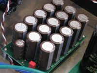
And now something special. F3 PCB version for 15x1000uF Elna silmic capacitors. Since MelonHead was the first who tried such setup I called it accordingly. As usual comments are wellcomed.
Pawel
View attachment F3_PCB_melonhead.pdf
Pawel
View attachment F3_PCB_melonhead.pdf
nice layout.
i would like to build the F3 myself and am still looking for te layout i whill use.
do you also have the BOM to go with it?
Mat
i would like to build the F3 myself and am still looking for te layout i whill use.
do you also have the BOM to go with it?
Mat
15x1000uF Elna silmic capacitors
Originally posted by Nelson Pass, January 23, 2009
Originally posted by Nelson Pass, January 24, 2009
Finished my F3 in the Fall of 2009. Obviously, the Master was trying to tell us something and he was right. Glad I took his advice. Have 6 more boards. If anyone is interested contact me.
Originally posted by Nelson Pass, January 23, 2009
... Probably the most contentious part is the big electrolytic at the output. If you could parallel up a pile of Elna silks or polypropylenes to form the output capacitance I think that would be the biggest improvement you could make parts-wise.
Originally posted by Nelson Pass, January 24, 2009
Trust me - people obviously are missing a big bet on the Elnas.
Finished my F3 in the Fall of 2009. Obviously, the Master was trying to tell us something and he was right. Glad I took his advice. Have 6 more boards. If anyone is interested contact me.
Attachments
...... Obviously, the Master was trying to tell us something and he was right.......
he's usually not trying ; he just say what he want to say

rest is on us
I like that pic of marching band 😉
why not go with electronic concepts unlytic 1000uf polypropylene? they are massive in size, can go right up to 2200uf. can get them occasionally on surplus auctions, even then they wont be cheap, but probably not as much as you would think and 16x 1000uf silmic isnt cheap either
Last edited:
Originally posted by Zen Mod
Zen Mod, glad you like the marching band. It plays beautiful music. I agree, when Mr. Pass speaks he knows what he's talking about and if we don't pay attention we may never know what we missed.
qusp said: why not go with electronic concepts unlytic 1000uf polypropylene?
The silmics were on sale and I got a good buy.
he's usually not trying ; he just say what he want to say
Zen Mod, glad you like the marching band. It plays beautiful music. I agree, when Mr. Pass speaks he knows what he's talking about and if we don't pay attention we may never know what we missed.
qusp said: why not go with electronic concepts unlytic 1000uf polypropylene?
The silmics were on sale and I got a good buy.
considering size of 1000uF Unlitics - maybe it's best to place them in speaker's stand
😀 well sure, if you are working them into the crossover why not make a feature of them and pot them in clear epoxy as stand?😉 or mass loading in speaker cabinet
Last edited:
Obviously, the Master was trying to tell us something and he was right. Glad I took his advice. Have 6 more boards. If anyone is interested contact me.
YES, I am happy that the Master confirmes this cluster-of-small-electrolytics approach. Till 2007 I was loosing all comparisons of my SE SS amps again the Linn topology amps, and only after I used a cluster of low-impedance smaller electrolytics, I have demonstrated definite advatages of SE topology to my friends. Even Jamicon WG and WL series, that are definitely not the best, solve the task. But, anyway, 50...100uF polypropylene shunt cap is obligatory. Since then, I use this approach in all new amps.
http://www.diyaudio.com/forums/pass-labs/145303-50w-version-zen9-6.html#post2421936
http://www.diyaudio.com/forums/soli...d-follower-99-hf-transistors.html#post2472063
http://www.diyaudio.com/forums/solid-state/185386-no-nfb-headphone-pre-amp.html#post2509272
Originally Posted by VladimirK
VladimirK, thank you for pointing me to raise a question that I haven't been able to answer since I'm still a novice who is still learning. Could you explain what happens when smaller electrolytics are used to form the capacitance in this particular place in the circuit, and why this approach results as Nelson Pass has said in "the biggest improvement you could make parts-wise." What is it that smaller electrolytics clustered in this way contribute to improve the sound that larger caps do not and how does this happen? I am very pleased with the sound of my F3. But then, I haven't heard one that uses "the big electrolytic at the output".
YES, I am happy that the Master confirmes this cluster-of-small-electrolytics approach....
VladimirK, thank you for pointing me to raise a question that I haven't been able to answer since I'm still a novice who is still learning. Could you explain what happens when smaller electrolytics are used to form the capacitance in this particular place in the circuit, and why this approach results as Nelson Pass has said in "the biggest improvement you could make parts-wise." What is it that smaller electrolytics clustered in this way contribute to improve the sound that larger caps do not and how does this happen? I am very pleased with the sound of my F3. But then, I haven't heard one that uses "the big electrolytic at the output".
- Home
- Amplifiers
- Pass Labs
- F3 Builders Thread