Originally Posted by VladimirK
VladimirK, thank you for pointing me to raise a question that I haven't been able to answer since I'm still a novice who is still learning. Could you explain what happens when smaller electrolytics are used to form the capacitance in this particular place in the circuit, and why this approach results as Nelson Pass has said in "the biggest improvement you could make parts-wise." What is it that smaller electrolytics clustered in this way contribute to improve the sound that larger caps do not and how does this happen? I am very pleased with the sound of my F3. But then, I haven't heard one that uses "the big electrolytic at the output".
I have got close to this "cluster-of-small-caps" solution by measuring the dielectric losses angle of various caps and clusters, at 10kHz frequency. If one composes the cluster from 680...1000uF low impedance caps, or Elna Cerafines, or Elna Silmics, I could state that no one single electrolytic cap, with the same capacity as the total cluster capacity, could have similar dielectric losses angle.
For the cluster, at 10kHz, the angle constitutes 20...40 degrees, while for the single cap it is usually close to 90 degrees.
This topic could be continued for very long, also discussing correlations between measurements and listenable effects.
I have wanted to mention something I have found when working with multiple small caps for ESR reasons. This sounds like a good place to do it.
In the output of SMPs supplies you generally need some serious ripple current capability. This requires low ESR/High Ripple caps. You also generally have a feedback point in the output. If you mount and layout copper such that the caps are all bunched up in one big piece of copper and your feedback point is in "any 'ol place" your regulation will suck! cap current balance will be as bad. The proper way to do it is to create a line of caps from the output inductor to the ouput connector. Your feedback goes at the end of the line. This is because there is DCR and L in the copper and cap leads and a filtering action like a CRCRCRCRCRC function if they are in a line. If they are bunched up in one tight little area, that may work but, not in the output of a good SMPs. What we are doing when we parallel caps in our amp output is probably wanting the opposite configuration. We actually want them all paralleled and not in a line?
Comments?
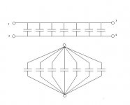
Maybe a picture will exhibit what I was trying to say better. If you connect the ouput L of an SMPs to pins 1 and 2 of the first picture and take the feedback and output from 3 and 4 you will get reasonable, stable behaviour. Expecting the same voltage across the group is wrong as this particular layout creates a CRCRCRCRC type of filter. What goes in at pin 1 as a sawtooth wave exits pin 3 with very little ripple at all. Again this is fine for a power supply filter but not what we are looking for when paralelling output caps for our amps.
If you try to configure your capacitor group more like the second picture you approach a more ideal group of paralell Cs without the CRCRC effects. The big question is, how do you do that? How do you lay that out on a PCB without the extra lead length and different copper distances?
😕
If you try to configure your capacitor group more like the second picture you approach a more ideal group of paralell Cs without the CRCRC effects. The big question is, how do you do that? How do you lay that out on a PCB without the extra lead length and different copper distances?
😕
Attachments
How do you lay that out on a PCB without the extra lead length and different copper distances?
😕
FLG--there's a somewhat similar analogy in RF, in which you can build dummy loads using resistors, where you want to keep lead length very short, especially at UHF frequencies and above. The "cluster approach works" well. Consider this......
On your main PCB, identify a single central "input point" for your capacitor bank.....from this one point, run a series of short radial PCB traces to each of your ## (pick a number) of capacitors, arranged in a circle around the "input point"..... Attach one lead of each cap to each one of the pads on the circle circumfrence. For the output of the capacitors, their leads would be pointing straight up, and above them, install a small PCB, with a central "output point", against with radial traces going to PCB pads arranged in a circle (same pattern as on your main PCB). Mount this small PCB on the capacitor output leads, and take your amp output from the central point on this small PCB. In effect, the capacitors are "sandwiched" between your main and small secondary PCB, and the all have the same lead length, arranged as compactly as possible.
As a compromise (isn't everything in life?.....) and if you have a LARGE number of caps, then use a radial configuration of two concentric circles on the PCBs.... sacrifices idential short lead length a little , but gives you better "packing density" of the caps.
'Wish I was an artist--I'd draw up a quick diagram for you....! Let me know if this helps.....food for thought, at least.....
Ken Mod, friend of Zen Mod.....
FLG - Do you mean something like on attached picture ? I drew two PCB for 8 caps. We can do two of them for 15 x Elna 1000uF caps plus additional one 220uF and screw them together to form 3D structure. Circle for 15 caps of 18mm diameter is to wide.
View attachment Cap_star_stack.pdf
View attachment Cap_star_stack.pdf
Furthermore we can put small 1uF film capacitor inside one of stacks of 8 caps, in the same way as the rest, i.e. one leg solder to the first PCB and second to another one.
Yes these suggested methods seem like the most efficient, thanks. There is always this other issue, I ussually have some giant 10-33uF axial film cap and I'm trying to paralell it with radial electrolytic caps. Compromises, Compromises.
I just thought I would suggest that layout thing with the high freq filter action and about how you probably should not, layout your parallel output cap group. It is very difficult to see this or current sharing happening on the bench.
I just thought I would suggest that layout thing with the high freq filter action and about how you probably should not, layout your parallel output cap group. It is very difficult to see this or current sharing happening on the bench.
I like the idea of star wired capacitors although it's not to be place directly on the PCB. It's so unusual but should work well. Thank you FLG for inspiring me. 🙂 Pawel
Elna silmic 1000uF/50V is 18mm in diameter, so you can put up to 28mm cylindrical film cap inside in this case. As on attachment.

Originally posted by Nelson Pass
These recent posts are interesting. Now if only Mr. Pass would weigh in and comment.
If you could parallel up a pile of Elna silks or polypropylenes to form the output capacitance I think that would be the biggest improvement you could make parts-wise.
These recent posts are interesting. Now if only Mr. Pass would weigh in and comment.
FLG - Do you mean something like on attached picture ? I drew two PCB for 8 caps. We can do two of them for 15 x Elna 1000uF caps plus additional one 220uF and screw them together to form 3D structure. Circle for 15 caps of 18mm diameter is to wide.
View attachment 216643
Nice diagram. This is what I was attempting to describe, although I was considering caps with leads on each ends--with the second (small) PCB located on top of the caps. Same concept, and the diagram describes it nicely. Agreed--for 15 caps (or so), the star cluster could work, but I'd probably go with two rings of caps--say, 5 on the inside ring, and 10 on the outter ring.... I'd have to sketch it, to see if this is the most compact arrangement. Again, just a concept we've used with non-inductive resistors to make compact dummy loads......
If your speakers are about 8 ohms, you don't actually need a 15,000uF o/p cap - half that is still perfectly satisfactory - can parallel a bunch of good quality film caps for a substantial "bipass" cap - I have 10 x 22uF Russian K73-16s across the DNM Slit Foil 10,000uF (by BHC) o/p cap at present and it's rather a good combination - I prefer the midrange sound of the Slit Foils in comparison to the Silmics but the bass is a bit "thinner" so changed the 40uF Auri film cap (C3) to an Obligato to compensate.
Lotsa fun and games, eh!
The leads are long enough on the Silmics to make 2 seperate "rings" for the + and - polarities as a "star" configuration with the + terminals towards the centre, etc and some plain sleeve to stop shorts - be a bit neat and no problem at all with a tape wrapping to provide insulation over the connections.
and yes - already written here few times - you can implement dedicated tweeter cap , connected before main output cap .
either internal one (cap) , or with additional ( live ! ) bind post for tweeter , for biwiring
either internal one (cap) , or with additional ( live ! ) bind post for tweeter , for biwiring
I've built Zen v9 with Nichicon KS 10 000uF at the ouput, and then F5 witout any capacitor in audio signal path. I noticed a difference. F5 goes a bit down at the bottom frequencies than Zv9.
Difference is not so pronounce but is there. So decided to use 15x1000uF Elna simlic to improve on that.
Difference is not so pronounce but is there. So decided to use 15x1000uF Elna simlic to improve on that.
Now "Melonhead" version for 15x Elna 1000uF +220uF stacked outside PCB and wired to it.
View attachment F3_PCBmelonhead.pdf View attachment ELNA15x1000uFCapStar.pdf
View attachment F3_PCBmelonhead.pdf View attachment ELNA15x1000uFCapStar.pdf
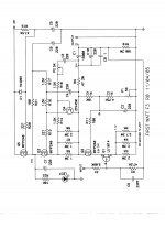
F3 schematic
Hi,
Anyone knows where I can find the schematic for F3? I've searched the firstwatt.com site, but I've found only the simplified one.
Hi,
Anyone knows where I can find the schematic for F3? I've searched the firstwatt.com site, but I've found only the simplified one.
Attachments
- Home
- Amplifiers
- Pass Labs
- F3 Builders Thread