You need to changes the "9V" to be closer to "8V" and get the drain of the LU closer to 3.5-3.6V...
😀
Yes, I know that (and mentioned the needed voltages in my post) but should I change the R5 to a smaller or bigger value as well because if i set the voltages with P1 now, the output DC will be something that it shouldn't.
Ok, so I tested it with 0.47ohm resistors (didn't have anything else at hand) in parallel/series combination and ended up with voltages 20.5/3.5/8.2. I guess this is about as close as I can get. I currently have five 0.47 resistors combined to a total of ~1.65ohms.
Combined how? 5 in paralell would be .094 ohms? Maybe .66 ohms or so for the LU Rs if I remember my experiments with this circuit...
I think it would be important to have a Vds on the LU device the same as N.P. had. Now that you have that we should try to get the LU current close to what he had (1.5A?). That means to get that you would need to adjust the current source Rs so the current source does the right current? Also you would need to get the LU device at that current? Just trying to help 😀
I think it would be important to have a Vds on the LU device the same as N.P. had. Now that you have that we should try to get the LU current close to what he had (1.5A?). That means to get that you would need to adjust the current source Rs so the current source does the right current? Also you would need to get the LU device at that current? Just trying to help 😀
Last edited:
3*0.47+0.23 in series i.e. three in series + two in parallel and then in series with the three. This multiple resistor thing is only a temporary solution to determine the correct value. The resistor value depends on the LU sample so if you had 0.66 ohms it doesn't mean I have the same. That value actually sounds quite low. According to the ZV9 article the resistor should be somewhere between 1...3 ohms. Mine is currently at about 1.65 ohms. The other channel is going to be closer to 2 ohms as the voltages were a bit closer to start with.
I don't really know what you mean by adjusting the current source resistor as this is not mentioned in the ZV9 article. Only thing that is mentioned is the correct voltages (although a bit different as the supply is 50V) and that you match that one resistor to your LU sample (this is also in the F3 schematic). I don't think that adjusting the current source resistor is discussed in this thread either.
I'm assuming that if you end up with the correct voltages at all points then your current is going to be about right as well.
Value of paralled R6, R7, R8 control current source. These are source resistors of Q3. As mentioned in ZV9 article voltage across them is 0.66V controled by Q4 (ZTX450). In Zv9 resistors R4,R5,R6 form 0.33R i.e. bias equals 2 amp. In F3 accordingly R6, R7, R8 should form 0.4R i.e. bias will be 1.65amp. Or you can change it as you like. It's described in ZV2 and ZV4 articles also.
If you've got problems in voltage lets check value of R12, R13 and P1 altogether.
If you've got problems in voltage lets check value of R12, R13 and P1 altogether.
Ok. So I have about 1.55 amps (0.62V over the resistors). Didn't measure the resistors so that's assuming they are exactly 0.4R when paralleled.
Are there any advantages when rising the bias for example to the 1.65 amps that you mentioned? I don't really need any more power.
Voltages are: left: 21/3.41/8.19 and right: 21/3.50/8.20. R5 left ~1.65 ohms and right ~1.88 ohms. I guess the left channel R5 could be just a little bit bigger (something like 1.7-1.75) to get it even closer to 3.5V but I can't make such fine adjustment easily with the resistors I have at hand. If I change it to 1.88 ohms (4*0.47 in series) it's too much. I guess those voltages are still pretty close?
Didn't measure the resistors so that's assuming they are exactly 0.4R when paralleled.
You'd better measure every resistor than assume something. Check value of R12, R13 also.
I'm not really equipped for measuring so small resistor values accurately. I think my meter has at least the same amount of tolerance as a 1 ohm 5% resistor.
If I calculate the maximum variance in resistance when the resistors are with 5% tolerance I should have a bias current between 1,47...1,63 amps when the voltage over the resistors is 0.62V.
Should the voltage over the resistors still be 0.66V even though the F3 uses a lower supply voltage than in the ZV9 article?
Last edited:
Should the voltage over the resistors still be 0.66V even though the F3 uses a lower supply voltage than in the ZV9 article?
This is referring to the R0 11/04/05 schematic that has 46V (50V in the ZV9 article). I also have a 46V supply.
Should the voltage over the resistors still be 0.66V even though the F3 uses a lower supply voltage than in the ZV9 article?
Page 3 - http://www.firstwatt.com/pdf/art_zen_amp.pdf
and Page 2 - http://www.firstwatt.com/pdf/art_zv2.pdf
nad Page 3 - http://www.firstwatt.com/pdf/art_zv4.pdf
To measure small value resistors connect them all in series with 1K resistor and to e.g. 15V voltage source or more, then measure voltage drop across each of them.
Ok. In those articles it was mentioned that one should arrive at about 0.66V so I guess I'm still "at about 0.66V" with my voltages (0.62 left / 0.61 right). Should I then just measure and adjust my resistors to arrive at the same current if I had 0.66V? So for example 1+1+1.5 ohms in parallel would give 1.65 amps when the voltage is 0.62V.
I have to say that in the current state I'm a little disappointed with the sound. My F5 seems easier to listen. My speakers are an easy load so running out of power etc. with the F3 can't be the cause for that. Would a slightly lower bias have this kind of an effect?
I have to say that in the current state I'm a little disappointed with the sound. My F5 seems easier to listen. My speakers are an easy load so running out of power etc. with the F3 can't be the cause for that. Would a slightly lower bias have this kind of an effect?
Last edited:
Probably not. Maybe someone else have something to say about it ?Would a slightly lower bias have this kind of an effect?
F3/ZenV9 and F5 have different sound signature. F3/ZenV9 have deeper soundstage and just little more musical at the cost of slight dimming of details. Any king of drum is better on F3 and not only that. But my F3 on 15xElna1000uF is bright nonetheless.
Maybe it would have also been good to test the the amp with the original 15000uf panasonic/220uf silmic/1uf pp setup to get a feel how the amp sounds as almost stock. Then I would also have something to compare the paralleled silmics with. Who knows maybe I might even prefer it like that instead of the 15x1000uF+1x220uF silmics. I already disconnected that 1uF Mcap Supreme yesterday and initial thoughts were that it was better without it.
However someone might prefer the sound with the mundorf as it pronounces the top end and maybe a bit of the upper midrange and gives more "attack". I still feel the top end is a little bright even without the mundorf.
Overall my F5 sounds more balanced and nothing doesn't stand out too much.
However someone might prefer the sound with the mundorf as it pronounces the top end and maybe a bit of the upper midrange and gives more "attack". I still feel the top end is a little bright even without the mundorf.
Overall my F5 sounds more balanced and nothing doesn't stand out too much.
Maybe it would have also been good to test the the amp with the original 15000uf panasonic/220uf silmic/1uf pp setup to get a feel how the amp sounds as almost stock.[/quote]
Thats what I'm doing, although I have a Zen9.
Thats what I'm doing, although I have a Zen9.
I haven't followed the whole thread (even though the F3 is one of my
favorite amplifiers).
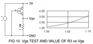
Did you adjust the value of the Source resistance against the Vgs figure of
the Jfet? I recall that I published a curve and some comments about this
on page 8 of the ZV9 article.
Also, you are looking for a Vds on the Jfet at around 2.5V.
😎
favorite amplifiers).
Did you adjust the value of the Source resistance against the Vgs figure of
the Jfet? I recall that I published a curve and some comments about this
on page 8 of the ZV9 article.
Also, you are looking for a Vds on the Jfet at around 2.5V.
😎
Attachments
Mr Pass,
I sent you an email regarding this test last week.
When applying the voltage to the test circuit, should I wait until the voltage settles (it just keeps climbing) or take the first reading on applying the voltage? The jfet heats up very fast, so it's not at room temp for very long.
Thanks,
Vince
I sent you an email regarding this test last week.
When applying the voltage to the test circuit, should I wait until the voltage settles (it just keeps climbing) or take the first reading on applying the voltage? The jfet heats up very fast, so it's not at room temp for very long.
Thanks,
Vince
It has been said somewhere already . Measure Vgs while Jfet is still at room temperature = no more than 2 sec in my experience. Or first reading after a second - short stable period before it climbs up - better.
room temperature = no more than 2 sec in my experience. Or first reading after a second - short stable period before it climbs up - better.
That's a fine line, but ok.
Thanks,
Vince
Did you adjust the value of the Source resistance against the Vgs figure of
the Jfet? I recall that I published a curve and some comments about this
on page 8 of the ZV9 article.
Also, you are looking for a Vds on the Jfet at around 2.5V.
😎
I couldn't test the jfet prior installing it to the amp (don't have a suitable power supply) but I adjusted the resistor value R5 to arrive at about 3.5V on the drain of the jfet and a about 2.5V drain to source (when the amp is warmed up). Ended up with values ~1.7ohms/left and ~1.9ohms/right. Output dc is 21V, supply rail is 46V and about 41V at the drain of Q3. Voltage over R3-R5 is about 1V and 0.62V over R6-R8.
I don't really know what happened but after trying out different value resistors and finally reverting back to the values mentioned in the previous paragraph the amp started to sound pretty damn good last night. Maybe there was a bad connection somewhere? My super tweeter might still be playing a bit rough sometimes but this might change once I connect it through the separate coupling cap. I already have it installed with a second set of speaker terminals but don't have another pair of cables.
- Home
- Amplifiers
- Pass Labs
- F3 Builders Thread