My favorite approach to that problem is to bootstrap from the average of input and output voltages of the opamp, by using a voltage divider between + and output pins. That means any signal swing must involve the output, and the supply is symmetrical about the signal voltages maximizing the available swing.Ya, I knew that version has problems. The bias current only has to be a couple mA since the base currents of the drivers peaks at about 1mA.
Mostly, I just remembered an important point about bootstrapping op-amps: You can not bootstrap them 100% because that leaves no op-amp output voltage slew wrt their supply pins which defeats the op-amp internal compensation, so assuming you are counting on that compensation, the result in instability.
You can use two dividers between + and output pins, and bias one from a current source and the other from a current sink, creating the voltage spread. Or you can use zeners from a single divider which is a little easier.
Also if you want output bootstrapping a bit of LPF can decouple the bootstrap signal enough to bring stability, although that makes a small phase shift.
Last edited:
Elvee,
After several misadventures in testing, and doing another set of boards, it's kind of working (I mean it doesn't burn, or blow fuses 🙂,
however first test with oscilloscope revealed oscillations at 5.1 MHz.
Now funny thing - I simmed this amp (a lot), and there were no oscillations.
After latest LTSpice upgrade, suddenly I see small oscillations!
This happens regardless of what transistors I use in the sim.
Remedy (at least in the sim) seems to be:
a) increase base stoppers on drivers to 100 Ohm
OR
b) decrease (or remove) 82pF capacitors going to ground.
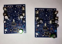
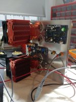
Drivers are soldered directly to the PCB, and output devices via short (5cm) wires. Input shorted to ground (shorting doesn't make any difference).
Drivers: TTC004B/TTA004B
Output: MJL21194/21193
Opamps: LT071 + LT1056,
2N5551/2N5401 + BC327/BC337
What you see on the chassis - fans, controller and voltage regulator are not connected/powered during the test.
Your suggestions would be appreciated.
After several misadventures in testing, and doing another set of boards, it's kind of working (I mean it doesn't burn, or blow fuses 🙂,
however first test with oscilloscope revealed oscillations at 5.1 MHz.
Now funny thing - I simmed this amp (a lot), and there were no oscillations.
After latest LTSpice upgrade, suddenly I see small oscillations!
This happens regardless of what transistors I use in the sim.
Remedy (at least in the sim) seems to be:
a) increase base stoppers on drivers to 100 Ohm
OR
b) decrease (or remove) 82pF capacitors going to ground.
Drivers are soldered directly to the PCB, and output devices via short (5cm) wires. Input shorted to ground (shorting doesn't make any difference).
Drivers: TTC004B/TTA004B
Output: MJL21194/21193
Opamps: LT071 + LT1056,
2N5551/2N5401 + BC327/BC337
What you see on the chassis - fans, controller and voltage regulator are not connected/powered during the test.
Your suggestions would be appreciated.
Attachments
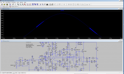
Here is how the oscillations look in the sim.
It's only visible on the emitters of output devices, the output is clean, for some strange reason.
Changing 82pF caps to 47pF (or complete removal) fixes it.
In practical terms - the easiest for me would be to remove 82pF caps from the board, no need to
even unscrew the PCB from the chassis...
It's only visible on the emitters of output devices, the output is clean, for some strange reason.
Changing 82pF caps to 47pF (or complete removal) fixes it.
In practical terms - the easiest for me would be to remove 82pF caps from the board, no need to
even unscrew the PCB from the chassis...
Attachments
Last edited:
It only oscillates with LT1056 opamp.
When I try TL071 or LF356, oscillations disappear.
Will test with other opamps, and continue my testing...
When I try TL071 or LF356, oscillations disappear.
Will test with other opamps, and continue my testing...
Last edited:
Interesting results: they show a convergence with mine.
The circuit is somewhat temperamental, but not in a nasty way: it is not going to fry your tweeters or the Zobel, but even a low-level oscillation is annoying and not tolerable.
The root cause looks difficult to pinpoint: as you noticed, everything seems to have some influence (even in Spice, the version influences the result).
The bootstrapping does seem to play a major role, but I have not been able to detect exactly in what way.
I am going to reexamine my own prototype, to try and find a definitive and reliable solution.
It is a promising amplifier, and if these relatively minor wrinkles can be ironed out, it will be a winner in the DIY sphere, because of it absence of quiescent current issues
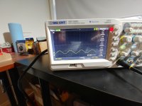
I proceeded with testing with LF356
Works flawlessly, at least on the oscilloscope.
See waves here:
http://www.slowbears.com/flickr/CurrentDump/
All done with 8 Ohm resistive load.
Very clean waves, as far as I can tell.
Completing 2nd channel, and then will try speakers with music.
Works flawlessly, at least on the oscilloscope.
See waves here:
http://www.slowbears.com/flickr/CurrentDump/
All done with 8 Ohm resistive load.
Very clean waves, as far as I can tell.
Completing 2nd channel, and then will try speakers with music.
Interesting results: they show a convergence with mine.
The circuit is somewhat temperamental, but not in a nasty way: it is not going to fry your tweeters or the Zobel, but even a low-level oscillation is annoying and not tolerable.
The root cause looks difficult to pinpoint: as you noticed, everything seems to have some influence (even in Spice, the version influences the result).
The bootstrapping does seem to play a major role, but I have not been able to detect exactly in what way.
I am going to reexamine my own prototype, to try and find a definitive and reliable solution.
It is a promising amplifier, and if these relatively minor wrinkles can be ironed out, it will be a winner in the DIY sphere, because of it absence of quiescent current issues
Nice and compact build (much nicer than mine!), clean oscillograms: it looks good, but it should work with any reasonable BiFet opamp, including the LT1056 (that was my intention anyway).
Were are nearly there: a bit more work, testing and head-scratching, and it will be good for general release
Were are nearly there: a bit more work, testing and head-scratching, and it will be good for general release
Were are nearly there: a bit more work, testing and head-scratching, and it will be good for general release
It is definitely the most complex amp I've built so far, also the most unusual amp:
if current dumping alone wasn't enough, it has 'floating' op-amps, and dual feedback
loops 🙂
Exactly what a marketing department might need 🙂
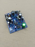
Also the PCB was a challenge, definitely double layer helped to keep all traces
short and compact.
So while you are 'revisiting' this, perhaps you can consider the next step - higher rails,
parallel output devices??
I have lots of MJLs left from the high-power circlophone project..
But I guess let's see how it plays real music first..
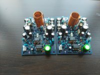
OK, 2nd channel finished. All bolted together, and playing music.
Sounds great. Runs cooler than Circlophone, despite higher rails.
2Nxxxx transistors are running at 50 degrees, LF356 runs at 40 degrees,
and TL071 at 34 degrees (with fans gently blowing some air on the board..).
1k resistors running at 44 degrees.
Drivers and output devices are cold -due to fan cooling,
and 2kg of aluminum.
Output DC offset: 5mV, identical on both channels.
Now it's gonna be tough choice between Circlophone and this one.
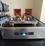
This black box with VU Meters under the amp, is a power supply, with
speaker protection and mentioned VU Meters.
I'm using it for all amps I'm testing.
It's +/- 80V 800W PSU, but I have auto-transformer in front
of it, so can adjust voltage as needed.
Kudos to Elvee for designing this amp! Thank you!
Now I'm gonna run it for couple of hours to 'break it in' 🙂
More pictures of the finished amp at:
http://www.slowbears.com/flickr/CurrentDump/
Sounds great. Runs cooler than Circlophone, despite higher rails.
2Nxxxx transistors are running at 50 degrees, LF356 runs at 40 degrees,
and TL071 at 34 degrees (with fans gently blowing some air on the board..).
1k resistors running at 44 degrees.
Drivers and output devices are cold -due to fan cooling,
and 2kg of aluminum.
Output DC offset: 5mV, identical on both channels.
Now it's gonna be tough choice between Circlophone and this one.
This black box with VU Meters under the amp, is a power supply, with
speaker protection and mentioned VU Meters.
I'm using it for all amps I'm testing.
It's +/- 80V 800W PSU, but I have auto-transformer in front
of it, so can adjust voltage as needed.
Kudos to Elvee for designing this amp! Thank you!
Now I'm gonna run it for couple of hours to 'break it in' 🙂
More pictures of the finished amp at:
http://www.slowbears.com/flickr/CurrentDump/
Attachments
Last edited:

Phew!: good to know that all ended well.OK, 2nd channel finished. All bolted together, and playing music.
I am not fully satisfied yet though: there are still unexplaned mysteries and oddities, and it should work with any regular BiFET opamp.
That's the beauty of the current dumping scheme: the only quiescent current is that of the class A amp.Sounds great. Runs cooler than Circlophone, despite higher rails.
Splendid build, a real artist's work.More pictures of the finished amp at:
http://www.slowbears.com/flickr/CurrentDump/
In the meantime, I have restarted my own prototype, which was still wired with the passive bootstrap, and I think I have pinpointed the reason of its marginal stability: when I move the collectors of the buffer/base-spreader transistors elsewhere, to the output of the class A amplifier for example, the amplifier becomes completely stable and doesn't require its small additional capacitor.
The fix could probably be beneficial to the other version too.
There are many bootstraps in this amp, and the collectors are probably a step too far.
After few hours of playing music, temperature of the LF opamp raised to almost 50 degrees,
and temperature of 2N5xxx transistors to 64 degrees.
I consider these numbers 'too hot', so I lowered the rails to 35V,
and sped up the fans a little bit.
That's the convenience of having adjustable autotransformer 🙂
Perhaps for next builds, TO-126 transistors can be used in place of 2N5xxx.
I guess MJE340/350 can be used?
Last edited:
Or use small cascode ? I think it's better to have 2 small transistors, rather than 1 big with heatsink...
Perhaps for next builds, TO-126 transistors can be used in place of 2N5xxx.
I guess MJE340/350 can be used?
Attachments
You can certainly substitute MJE340/50, or MPSW42/style transistors, if you find 64°C excessive (I don't).
The cascode would require additional components and would waste 1~ 2V of output swing: not very advantageous
The cascode would require additional components and would waste 1~ 2V of output swing: not very advantageous
I have made serious, comprehensive tests to understand the (marginal) stability issues.
I came to a conclusion: they originate mainly from two elements: the floating second-stage amplifier, and the diamond buffer/base-spreader, in particular the collectors connection.
The second stage is vulnerable, because the whole of the ambient world is "hot": as it sits at ~the output potential, each of its nodes sees a parasitic capacitance connected to a 100Vpp source, and even with femtofarads of capacitance, it is sufficient to cause an unwanted ingress.
The nodes include the inputs, of course, but not only: auxiliary pins like balance or compensation are also a possible path.
It is possible to control the impedance level at the inputs, but the auxiliary inputs can have a significant impedance/sensitivity when left open.
To mitigate the issue, guarding can (and should) be used: it would connect to Vee or Vcc of the opamp.
The auxiliary inputs can be disabled, but in a non-intrusive manner.
The exact method depends on the opamp type.
Balance pins could be shorted with a cap (to avoid disturbing the DC), and this will eliminate most of the differential perturbations in an "agnostic" way: a LF411, LF356, LT1056, TLO71 can be treated in the same way.
However, this does not eliminate common-mode ingress, which can be significant: balance pins act as secondary, low grade inputs and their CMRR is not very good.
For that reason, it is preferable to use two capacitors connected to the "neutral": the neutral can be Vee or Vcc, depending on the opamp variety.
The small 2.2pF cap on the + input compensates for the capacitance to the - input (which causes positive feedback), but it doesn't do anything for the other causes which is why killing them at the source is recommended.
The buffer is another source of problems, mainly because the collectors are bootstrapped.
It would be possible to eliminate this stage completely, but this would require a much higher current from the opamp, and the voltage-shifting task would have to be done in a much less satisfactory way.
The boostrapping of the collectors is certainly not required, but it is convenient: otherwise, the transistors would need to be rated for the full supply voltage, and they would dissipate a non-negligible amount of power, requiring cooling and thermal connection with the drivers.
It is possible with TO126 transistors, and I have included examples involving direct connection to the rails.
Many configurations are stable and usable, but I have retained four of them: the most promising, advantageous, stable and rational.
Two use the active bootstrap, and two a passive bootstrap.
All are remarkably well-behaved and tolerant.
I made most of the test without the input stage: it has nothing to do with the problems, and it can even hide them, by acting as an active compensator.
Even when the voltage amplifier is not stable on its own, it can be stabilized when included in the global loop.
Although it works, it is not healthy: the amplifier has not been designed that way, and each stage should be stable in isolation.
When the global loop is closed, things become even better
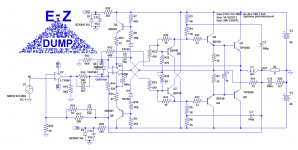
The first variant is very similar to the last active version; remember though that capacitors should be added on the balance pins (they do not figure on the model). 10 or 22nF is OK:
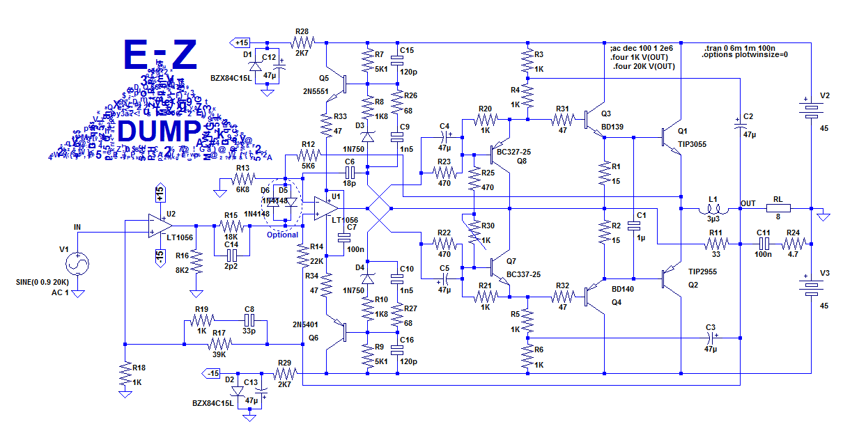
The second active version has the collectors of the buffers tied to the rails, and many capacitors deleted:
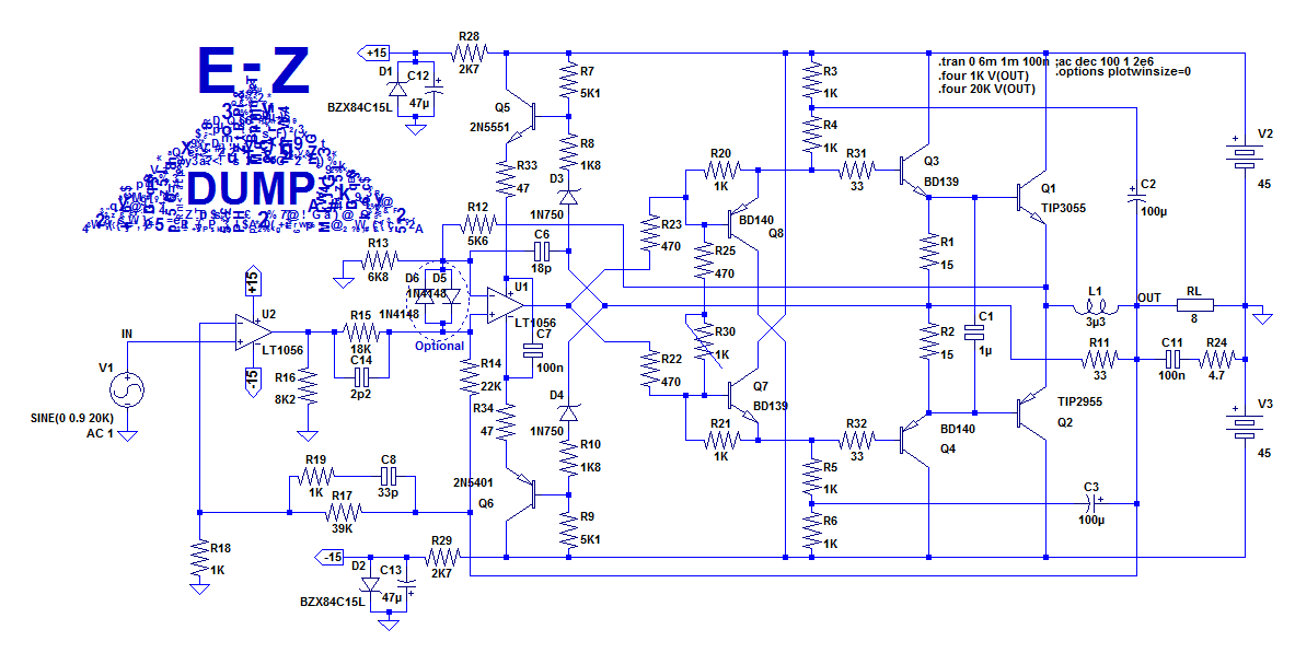
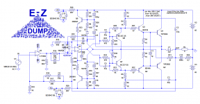
The first passive version has the buffer's collectors filtered:

It offers an excellent tradeoff.
The second passive version has the collectors connected to the rails:

The connection of the balance bypass capacitors depends on the opamp:
LF356: Vcc
LT1056: Vcc
LF411: Vee
TLO71: Vee
Etc...
The second active version has the collectors of the buffers tied to the rails, and many capacitors deleted:
The first passive version has the buffer's collectors filtered:
It offers an excellent tradeoff.
The second passive version has the collectors connected to the rails:
The connection of the balance bypass capacitors depends on the opamp:
LF356: Vcc
LT1056: Vcc
LF411: Vee
TLO71: Vee
Etc...
Attachments
Didn't know balance pins can be used for compensation (?), I thought they are only for setting 0mV offset..
I'm gonna sim all these versions.
All other things being equal, from building it perspective,
passive v1 looks the best to me. Smaller count of parts, and small,
cool-running transistors.
So the question is 'what is the trade-off'?
Active vs passive, and buffer connect to rails vs. connected to drivers?
I guess I'll build one of them, once I'm done with Alpha Nirvana amp (chassis almost ready),
and then - I got tired (lack of time!) of building new chassis, heatsinks, fans, etc..
for each amp I'm building, so I'm planning to build one 'platform':
chassis with fans and 1 set of N/P BJTs and 1 set of N/P Mos transistors bolted on,
so the amp board(s) can be plugged on on it via pin/header connectors..
PSU is already 'outsourced'.
Will standarize all PCBs to fit chassis connectors.
Also, all this hardware will take less space, and will save $$ 🙂
My current-dump (BTW, this amp deserves a name!) amp has been running 10h a day since it was build, and works perfectly as -is, playing all kinds of music.
Excellent, cool running amp, with best simmed distortion numbers I've seen. Would be nice to measure THD on it..
Their normal use is to set the offset (they sometimes have a double role of offset and compensation), but since they can influence the output voltage (that's their purpose after all), they can act as secondary inputs (in general low gain and low impedance), and anything capacitively coupled can inject perturbations.Didn't know balance pins can be used for compensation (?), I thought they are only for setting 0mV offset..
In general, it isn't a problem, because it is rare to have a 100Vpp HF source next to the OS pins, but with the floating configuration, all of the environment is "hot".
One of the pins is an inverting input, and the other non-inverting, and if the capacitances are balanced, the effect should cancel, but controlling parasitic capacitances smaller than 1 pF is difficult, and the CMRR is not very good: a single cap across the inputs was not capable of killing the ingress completely.
For some obscure reason, the sim shows a marginally higher THD for the passive, but I don't think it has a real significance.All other things being equal, from building it perspective,
passive v1 looks the best to me. Smaller count of parts, and small,
cool-running transistors.
So the question is 'what is the trade-off'?
The connection to the rails is more demanding (and also has a marginally higher THD), but it eliminates completely the stability issues at this level (the RC-filtered version is quite good though)Active vs passive, and buffer connect to rails vs. connected to drivers?
Sounds like a good plan for a compulsive builder!I guess I'll build one of them, once I'm done with Alpha Nirvana amp (chassis almost ready),
and then - I got tired (lack of time!) of building new chassis, heatsinks, fans, etc..
for each amp I'm building, so I'm planning to build one 'platform':
chassis with fans and 1 set of N/P BJTs and 1 set of N/P Mos transistors bolted on,
so the amp board(s) can be plugged on on it via pin/header connectors..
PSU is already 'outsourced'.
Will standarize all PCBs to fit chassis connectors.
Also, all this hardware will take less space, and will save $$ 🙂
Yes, it would be nice, but with my current means of THD measurement, it would be difficult: multi-loop amplifiers like this one can achieve extremely low THD levels requiring subtraction + passive filtering before the actual measurement.My current-dump (BTW, this amp deserves a name!) amp has been running 10h a day since it was build, and works perfectly as -is, playing all kinds of music.
Excellent, cool running amp, with best simmed distortion numbers I've seen. Would be nice to measure THD on it..
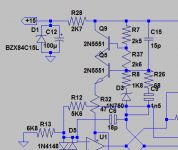
I'm getting ugly spikes in Q3/Q4 current..
Passive ver. 1
Final results are good, as far as I can tell, but original amp
didn't have these spikes...
Looks like they are caused by R10/C9.
Increasing R10/R26 to 100Ohm removes spikes, and lowers THD (at least at 1kHz).
Passive ver. 1
Final results are good, as far as I can tell, but original amp
didn't have these spikes...
Looks like they are caused by R10/C9.
Increasing R10/R26 to 100Ohm removes spikes, and lowers THD (at least at 1kHz).
Attachments

Last edited:
- Home
- Amplifiers
- Solid State
- EZ-Dump: dump your current without really trying