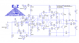
Note that the Russian R10+C9 is BOTH op-amp degeneration AND the source of positive feedback, guaranteed to be some fraction of the negative feedback.
And the supply rails are exactly the negative divider times the op-amp supply which may be required given that C9 blocks low frequency positive feedback.
Also note that the drivers are the same parts as the outputs, possibly for thermal tracking match.
I'm not convinced that "base stoppers" are always a good idea: What are your thoughts about them?
Member
Joined 2009
Paid Member
base stoppers might protect against thermal runaway, think of them as equivalent to an Re
Last edited:
I don't like them either: if they are necessary, it is a symptom that the physical implementation is not optimal (or another shortcoming), and they introduce unwanted effects, like parasitic poles eating up some of the global stability margins (mostly for MOS amps, but BJT's aren't immune).I'm not convinced that "base stoppers" are always a good idea: What are your thoughts about them?
Even in switching circuits, I try to avoid them, as they tend to ruin the edges.
base stoppers
Exactly. Wiring to a heat sink mounted devices can pick up signal from nearby currents so a damper helps, or the driver is inductive creating an LC tank with the Miller cap, or maybe the pole from the power device is not dominant enough so adding the resistor moves it down, or the VAS pole goes away during clipping leaving local feedback to oscillate. I have seen ferrites on the leads of TO220 MOS for similar reasons. Some fast power devices have physical designs that create their own unstable feedback. I'm pondering just which lead should have a ferrite, maybe the emitter/source to avoid making a Colpitts oscillator?
Exactly. Wiring to a heat sink mounted devices can pick up signal from nearby currents so a damper helps, or the driver is inductive creating an LC tank with the Miller cap, or maybe the pole from the power device is not dominant enough so adding the resistor moves it down, or the VAS pole goes away during clipping leaving local feedback to oscillate. I have seen ferrites on the leads of TO220 MOS for similar reasons. Some fast power devices have physical designs that create their own unstable feedback. I'm pondering just which lead should have a ferrite, maybe the emitter/source to avoid making a Colpitts oscillator?
In principle, the emitter is ~β times more effective than the base, and that's generally where they are
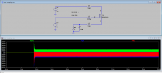
Lead coupling
This simulation illustrates the potential problem with transistor lead coupling. This example deliberately exaggerates the problem but the point remains. Changing the coupling polarity and inductance can be used to simulate the ferrite placement.
This simulation illustrates the potential problem with transistor lead coupling. This example deliberately exaggerates the problem but the point remains. Changing the coupling polarity and inductance can be used to simulate the ferrite placement.
Attachments
Elvee, just wanted to check with you - MJL3281 + MJL1302 should be fine for
output devices, right?
Or better stick to MJL21193/94 ?
output devices, right?
Or better stick to MJL21193/94 ?
The 3281/1302 should be OK, but if they are too nervous for the circuit, you can always fall back to the 21193/31194
Elvee,
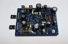
Have this amp (passive version) up and running.
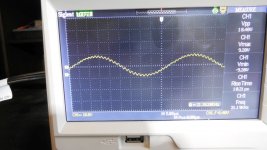
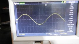
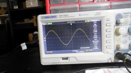
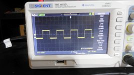
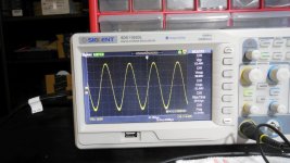
All smooth, but - small problem with waves - there is some modulation on every wave. I noticed that all waves looked 'thicker'.
All with 8 Ohm resistive load, 42V rails.
Same output devices as before: MJL21193/4.
And with two 22nF caps for 2nd opamp (LF356) to +Vcc frm pins 1 and 5.
See images.
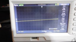
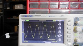
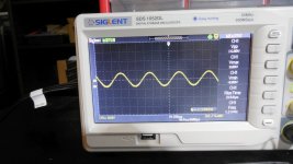
Most interesting are the last three photos when I zoomed to show the modulation.
Last image is a zoom at 1kHz sine.
Have this amp (passive version) up and running.
All smooth, but - small problem with waves - there is some modulation on every wave. I noticed that all waves looked 'thicker'.
All with 8 Ohm resistive load, 42V rails.
Same output devices as before: MJL21193/4.
And with two 22nF caps for 2nd opamp (LF356) to +Vcc frm pins 1 and 5.
See images.
Most interesting are the last three photos when I zoomed to show the modulation.
Last image is a zoom at 1kHz sine.
Attachments
-
 DSCN0192.JPG224.2 KB · Views: 152
 -
 DSCN0191.JPG231.5 KB · Views: 135
 -
 DSCN0190.JPG225.4 KB · Views: 129
 -
 DSCN0188.JPG215.4 KB · Views: 131
 -
 DSCN0187.JPG225.5 KB · Views: 348
 -
 DSCN0186.JPG213.1 KB · Views: 357
 -
 DSCN0180.JPG217.6 KB · Views: 371
 -
 DSCN0179.JPG224.5 KB · Views: 382
 -
 DSCN0178.JPG212.3 KB · Views: 370
Last edited:
Tried with LT1056 - same thing, but amplitude of oscillations is bigger.
These oscillations are present at the output of the 2nd op-amp,
but not on the output of the 1st op-amp.
Also - 270pF capacitor (C7) is going to signal GND on my pcb.
That was my guess - to use signal, not dirty GND. Maybe it should go to
dirty GND?
============
There is also another difference between my previous (active EZDump) build and this one:
shifter transistors in 1st build were BC327/337 - same as in your sim.
In this build I used KSA992/KSC1845 - and when I was re-trying the sim this,
it doesn't work. When I tried to sim with BC546B/556B - this also doesn't work - oscillates in strange way.
I thought any small transistor pair will be ok for shifter transistors, can you confirm?
Last edited:
Correction: BC546/556 work fine in sim, but KSA992/KSC1845 - don't.
No idea if this is related to the oscillations I'm having..
No idea if this is related to the oscillations I'm having..
See images.
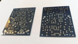
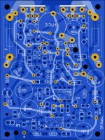
PCB is almost the same as for the 'active' EZDump amp built several months ago (and still working perfectly) , small changes have been made to acomodate simplified 'passive' scheme.
Asc file attached.
PCB is almost the same as for the 'active' EZDump amp built several months ago (and still working perfectly) , small changes have been made to acomodate simplified 'passive' scheme.
Asc file attached.
Attachments
Minek, I am just back from the clinic, where I had to stay ~4 times the initially planned duration, and had very unpleasant adventures.
Now, I am (hopefully) finally back home, but I am still a bit shaken, and it will take some time before, I can examine your problems
Now, I am (hopefully) finally back home, but I am still a bit shaken, and it will take some time before, I can examine your problems
Elvee, good to have you back! Don't worry, the most important thing - you are OK. Amp is not important, and can wait. Wish you quick and complete recovery!
- Home
- Amplifiers
- Solid State
- EZ-Dump: dump your current without really trying