I think you have an error in PCB layout.
Q4 & Q5 collectors are connected together.
So the bias circuit won't work.
Q4 & Q5 collectors are connected together.
So the bias circuit won't work.
If Q8 does not turn on then it's voltage regulator function will not be in operation.
That would leave a high voltage across the Vbe multiplier.
Yes, reduce R13 to 2k2, You could even reduce R13 as low as 1k5, but any value from 1k5 to 2k2 will do the job.
There is something else going on.
A short across the Vbe multiplier?
BTW.
the ratio of R13 : R13+R35 sets the voltage ratio of the multiplier.
Vmultiplier max ~ 2k2+330 /330 *Vbe = ~7.6*Vbe this is comfortably above the 4*Vbe across the output stage to just turn on all four driver and output devices.
The minimum Vmultiplier ~ 2k2+330+1kVR / 330+1kVR = ~2.7Vbe
This is comfortably below 4*Vbe, but does leave a significant voltage across ther driver bases. This is the part that is not working. Find the circuit assembly error.
Last edited:
And follow the advice in recent pages about the light bulb protection method for retesting after you have sorted the board out. I agree with the comments in the last two posts.
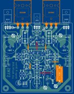
View attachment error.bmp
The above image shows where I think the PC has a problem,
it looks like it shorts out the bias network.
The above image shows where I think the PC has a problem,
it looks like it shorts out the bias network.
Thank you guys,
I've been workin on the pcb all day, I suspect something went wrong.
Thank you Symon, missed that part. I will check on my work again and see if it fixes the problem.
Albert
I've been workin on the pcb all day, I suspect something went wrong.
Thank you Symon, missed that part. I will check on my work again and see if it fixes the problem.
Albert
Good news guys!
Cutting the tracks per Symon's post, bias adjust worked! I am planning to put back the original bias circuit values....will also try to reduce R13 to 2k2, but it is working now.
Again, thank you all!
Cutting the tracks per Symon's post, bias adjust worked! I am planning to put back the original bias circuit values....will also try to reduce R13 to 2k2, but it is working now.
Again, thank you all!
Hi guys!
Going back to my SymAsym build, I can't make the bias adjust to work
It worked the first time I power the amp, set it to a low 20mv across both 0.22r just for a test run. Following the other day I cannot measure any dc voltage across the re and at the bases of the drivers, totally zero, none. Playing music with it, it will work and I can get DC voltages but without music it goes back to zero. I thought I messed up the vbe 1k trimmer because I am hearing faint clicks while repeatedly doing the process.
I decided to run a simulation of the amp and made new values at the bias circuit for use with a 5k trimmer (believing I busted my last 1k trimmer but never bothered to check it off board) but after placing the new values on board and adjusting the trimmer per simulation result, it still didn't work. 😕
Attached is a revised pcb lay-out and my schematic. Notice the addition of a small resistor at the ltp emitters (R36), this reduces a few CCS current because DC transistor condition in sim shows that one trannie is hot (Q6 tied to 22k-ground). The 2.2k addition seemed to lower the THD figure (in simulation).
My actual build is working nicely, sonic is very good, dead silent and no turn on/off thump... I just can't figure out why biasing stopped working or is not working. I have check the drivers, vbe bias and output trannies but found no indication of any defects....any ideas what has gone wrong and where to check for possible fault?
BTW I am using c5200/a1943 and c5171/a1930(drivers), DC offset is -12mv (no matching done).
Regards!
Albert
Hi,
this 2 point should be open circuit.
Attachments

hi everybody.
i can't find anywhere mjl15030/15031. any suggestion for replace these parts?
Would be bd139/140 good?
regards
i can't find anywhere mjl15030/15031. any suggestion for replace these parts?
Would be bd139/140 good?
regards
mje15032/33, or mje15034/35, all made by ONsemi.
In general one does not need the 8A rating of the 15030/31/32/33 for driver stages.
The 4A rating of the faster 15034/35 is adequate for big Power Amplifiers.
In general one does not need the 8A rating of the 15030/31/32/33 for driver stages.
The 4A rating of the faster 15034/35 is adequate for big Power Amplifiers.
Hi guys. I've got a little problem over here. I've messed up my measurement. By mistake I used 2 mica disks under every MJ on the alu-L. So I've unsoldered them and changed it. All again in were working totaly fine, but I wanted to readjust the voltage above the emitter resistors. And than it happend, I've got a shorting while measuring. I've got contact with one measuring tip and the alu-L... so now there is a indian smoking signal every time I power the TO3 on ( the 22R Resistors ). 
 With a diode tester I've measured the base-emitter diode/Voltage which now equals 290mV ( functioning channel 2 shows around 500mV ), so they are trash now, huh? Does anyone think there could be another mistake or is the "only thing to do now" buying new MJ's and change them? Thanks for your help! 🙂
Cheers,
Buckitronic
With a diode tester I've measured the base-emitter diode/Voltage which now equals 290mV ( functioning channel 2 shows around 500mV ), so they are trash now, huh? Does anyone think there could be another mistake or is the "only thing to do now" buying new MJ's and change them? Thanks for your help! 🙂Cheers,
Buckitronic
Just to confirm they are dead, check continuity between collector and emitter,
should be open circuit in both directions. It's a common failure to burn through the base junction, so transistor becomes a short circuit between collector and emitter but retains slight diode function between Base and emitter.
If they don't measure shorted, then check boards make sure nothing else has shorted to cause the problem.
Thank you Symon, its a shorting... I'm realy to stupid to measure without destroying anything... does someone maybe know a trustful person/merchant where I could buy a matched NPN and PNP pair of them? Better from the EU/Germany, but without big shipment costs other countrys would also be possible.
Cheers,
Buckitronic
Cheers,
Buckitronic
Not sure exactly which devices you are using, you mentioned TO3 case?
Getting Matched pairs can be expensive, and limits the number of suppliers.
I think others have commented that you could buy a number and then pick the best pairs. I've done this my self when building a JLH Class A.
Getting Matched pairs can be expensive, and limits the number of suppliers.
I think others have commented that you could buy a number and then pick the best pairs. I've done this my self when building a JLH Class A.
I've used the MJ21195G and 96G as transistors. And I would rather pay a bit more for the matched ones as for a a bag of transistors and measure them. First I dont have any device for measuring the Hfe and second I dont have so much money for a say 10 pieces of each NPN and PNP, just a normal student. 
Cheers,
Buckitronic
Cheers,
Buckitronic
Hello there, I would like to build a second Sym Asym Black Beauty and i'm asking myself if there's a list or something which transistors I also can use except the ones who are described in the BB Manual from Rudi_Ratlos ?
Hi Buckitronic,
Those parts are generally close to each other. I still check for Beta match, but these days it has been mostly for confirmation and maybe to get them even closer in characteristics.
-Chris
Those parts are generally close to each other. I still check for Beta match, but these days it has been mostly for confirmation and maybe to get them even closer in characteristics.
-Chris
Hi Mace Horny,
If you read some of the thread, other transistors were discussed along with the advice that if you do change transistor types, you need to ensure that the amp doesn't oscillate or show instability. You need an oscilloscope and a sine wave generator. A sound card could work. Also try a square wave test, all into a dummy load.
The above is also needed when repairing amplifiers. Things get interesting when you are working on higher powered amplifiers! Skip this step at your peril.
-Chris
So you think I just should buy 2 types of NPN and PNp and all should work out well? Would be a desirable solution. 😀
Cheers,
Buckitronic
Cheers,
Buckitronic
Hi Buckitronic,
Well, if that's how you want to build it, go ahead. I would buy a few extra in case there are a couple off spec. As for what types, you can read up on which worked and whick didn't. I used the excellent MJW0302A and MJW0281A. If you do read, you might come across where I mentioned these, and also that I was able to run them at far lower bias to achieve very low distortion.
I don't think you can get those anymore, so see what everyone else used.
-Chris
- Home
- Amplifiers
- Solid State
- Explendid amplifier designed by Michael Bittner, our MikeB