There is a beautiful PCB of the SYMASYM, being offered in a group-buy of the German AAA-forum. This group-buy is authorized by Michael Bittner. If somebody likes to have this PCB: write me a PM please and I will ask the German "Group-buy Thread" owner for some PCBs.
PM sent. They look good.
Is this the BOM for the newer German AAA SymAsym amp?
http://www.kubusmaximus.com/symasym...hp?media=doku_symasym_t-network_juli_2010.pdf
Mein Deutsch ist nicht so gut. 😉 But I don't seem to see the 1k ohm multi-turn pot in this list. Interesting. Also think that the discussion list is here:
symasym5 - Phono - Restauration und Selbstbau - Analog-Forum
http://www.kubusmaximus.com/symasym...hp?media=doku_symasym_t-network_juli_2010.pdf
Mein Deutsch ist nicht so gut. 😉 But I don't seem to see the 1k ohm multi-turn pot in this list. Interesting. Also think that the discussion list is here:
symasym5 - Phono - Restauration und Selbstbau - Analog-Forum
Hello! I am newbee at electronics,have a little something assembled by my hands,some basic knowledge and uni-meter(V-A-O meter). I am reading posts here for quite some time and i still haven´t found answer to a question i have... I´ve completed two pcb´s of sym/asym5.3 asuming that i allready have proper supply,but when it came to that i found out that it´s not +/-36 VDC but +/-42VDC. Is it safe to connect sym/asym5.3 to that level of a supply or i will have to make a voltage regulator to decrease a voltage level (if taking off a few rounds from a transformer turns up as inposible)? Sorry for my bad english,i don´t use it or write as much as i am listening to it... Thanks up front!
Aleksandar M
Aleksandar M
Last edited:
...i found out that it´s not +/-36 VDC but +/-42VDC....
Hello Aleksandar,
a good, simple and cost effective way around it is to use a capacitance multiplier (see attached picture). You'll lose 4V (to get +/-38V) and the sound of your amp will benefit too.
The schematic shows a circuit needed for one channel. MOSFETs can be bought at kelco.rs
Attachments
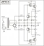
Thank you very much for yor answer my neighbour! 🙂 I will try to open the transformer and take off a few rounds if it is posible-i haven´t tried yet-and if the primary coil (220V) is over the secondary coil I will do either as You suggested to me,or something that APEX suggested at ES-forum(possible here too) and it looks like this...
Attachments

Last edited:
Yes, series regulator is an option too, but it's made to keep the PS voltage at fixed value. Since symasym is AB class amp the rail voltage will sag depending on the load (output power) and you'll have to set the regulated voltage lower (depending on your transformer's power and elko's quality) to avoid the situation where rail voltage sags too much. Cap. multiplier will always give 4-5V lower rail voltage no matter what is the unregulated input voltage.
Last edited:
OK,that sounds like a very good reason,very helpfool text too! I have a 350VA transformer(should be enough for 8 Ohm load,and a bit tight or for a 4 Ohm load) and a bunch of (4 x 2200uF,2 x 4700uF and 2 x 6700uF) capacitors. Should be enough to push two channel of symasym I guess. The transformer I have is not bifilar wounded so it is not possible to decrease output voltage without a lot of work. I will do as You said that it would be smart to do. I will have to make two of capacitor multiplier because... ? IRFP240/9240 has 150Watts of power,and if there is 4V at drain/source,and let´s say 10A drain/source it would be 40Watts of power so I guess the power is not a reason? Thanks!
... I will have to make two of capacitor multiplier because... ?
1. MOSFET's Vds depends on Id and AB class amps tends to draw current in peaks corresponding to music being played so it would be wise to avoid great Vds fluctuations.
2. You'll get better channel separation/less interaction through PS.
The MOSFET's low output impedance may cause a lot of interaction if 2 channels were used with the same multiplier.
The BJT regulator would have less output impedance, but you would have to parallel multiple BJTs to get the same power capability of the MOSFET.
- keantoken
The BJT regulator would have less output impedance, but you would have to parallel multiple BJTs to get the same power capability of the MOSFET.
- keantoken
OK than I ´ll do as you suggested to me. Those were two very good reasons why not to use one,but two capacitor multiplier. Thank you both very much! I beleive that soon there will be some hearing impressions by me and my sample of symasym. I have started to assembling it because i had large enough heat disipator,bunch of capacitors,large transformer(turns up with too high secondary voltage 🙂 🙂 ),box of some old amplifier and enough of time so I said to my self "Why not?" Oh yes,and a friend of mine,Boris from Sarajevo had sent me PCB´s and recomandation to do it,so,here I am... Thanks again to both of you!
Those are some new moments... So I don´t have to make any changes,just to connect it to the existing supply +/-42VDC and enjoy? GREAT! 🙂 Maybe only to change input transistors MPSA18 for 2N5551 due to higher supply voltage?
I haven´t seen pinkmouse´s post before i wrote post earlier...still new to this forum,sorry...
... Maybe only to change input transistors MPSA18 for 2N5551 due to higher supply voltage?
And the resistors. 😉
Hello to all,
Is there someone kind enough to point me where the PCB file for symasym5 amp? I am interested to build this amp and I hope Sir Alex MM would be kind enough to make the PCB layout if there's no one available... And please make the pcb layout for lasertoner transfer in pdf.
I hope I'm not asking too much for this...
Thank you so much in advance!
Blueice23
I am interested in building the Symasym 5.3 using a 25-0-25 transformer (or 2).
After reading the project page and some of this lengthy thread, I am a little confused as to whether this amp can be input from a preamp (with the basic amp circuit as shown on the project page).
Can someone enlighten me if changes to the circuit are required in order to use a preamp?
Thanks
Peter
After reading the project page and some of this lengthy thread, I am a little confused as to whether this amp can be input from a preamp (with the basic amp circuit as shown on the project page).
Can someone enlighten me if changes to the circuit are required in order to use a preamp?
Thanks
Peter
The Power Amp does not need to be changed to allow a Pre-Amp to feed it.
The Power Amp is designed to receive a signal from a Source and amplify it, to feed current to a speaker.
The Power Amp is designed to receive a signal from a Source and amplify it, to feed current to a speaker.
- Home
- Amplifiers
- Solid State
- Explendid amplifier designed by Michael Bittner, our MikeB