Meaning I sould not replace the cap?There is an exception - if you put a high value cap on the amp PCB, and it is supplied by unregulated voltage with ripple, then high impulse ripple current flows into the PCB ground and it can induce quite high noise (hum) voltage and worsen S/N.
Regards,
Paulo.
Now that this thread is alive again, can anyone explain to me why this amplifier is one of the few (the only one to my knowledge) where you connect the speaker return to the amp board instead of the star ground point?
And what happens if the SymAsym blows a fuse, either - or + rail? Does the output stick to the remaining rail or does it behave nice. I need to know if DC speaker protection is a must or might be skipped for starters...
And what happens if the SymAsym blows a fuse, either - or + rail? Does the output stick to the remaining rail or does it behave nice. I need to know if DC speaker protection is a must or might be skipped for starters...
Now that this thread is alive again, can anyone explain to me why this amplifier is one of the few (the only one to my knowledge) where you connect the speaker return to the amp board instead of the star ground point?
And what happens if the SymAsym blows a fuse, either - or + rail? Does the output stick to the remaining rail or does it behave nice. I need to know if DC speaker protection is a must or might be skipped for starters...
This might explains some... Star Grounding
OR here:
Paul Ruby Amplifiers
I studied mike's "symasym" board and it is a secondary "star" , along with another (another channel), it then connects to a central star located at the main capacitor bank/trafo CT.
I have observed a larger version of this amp with a blown fuse , didn't blow the speaker , didn't blow any OP devices. A DC protect circuit couldn't hurt, but all my equipment is doing well after 13 months and much abuse.
OS
Meaning I sould not replace the cap?
Regards,
Paulo.
You should rather increase the PSU filter cap than the PCB board cap. The reasonable value of PCB bypass cap is 100uF - 220uF. If you go higher, you would get into S/N problem.
regards,
But the schematics say C12/13 are 1000uF! Now I'm confused...😕he reasonable value of PCB bypass cap is 100uF - 220uF.
You should rather increase the PSU filter cap than the PCB board cap. The reasonable value of PCB bypass cap is 100uF - 220uF. If you go higher, you would get into S/N problem.
regards,
What if any large caps (1k - 4.7kuF or up) have a star grounding independent from the VAS/input stages.
On that note , would not the symasym's output device switching return a lot of ripple to it's local star ??
OS
Maybe, in a very careful PCB design. BUT, in most cases, you would measure an increase of mains level component and multiples. Only in case of regulated PSU (preamps) there is no problem with large PCB rail caps.
So you're saying I should replace those caps but for lower values? Is it OK for the Symasym or should I follow the BOM?I see, but it does not change my opinion.
Thanks.
Maybe, in a very careful PCB design. BUT, in most cases, you would measure an increase of mains level component and multiples. Only in case of regulated PSU (preamps) there is no problem with large PCB rail caps.
"regulated PSU ?" You mean like a capacitance multiplier or other active regulation ?
The reason I ask , is that I am about to "split" a symasym type voltage stage away from the "Dirty" OP board. I might lose a few volts with the multipliers , but I have 70+ to "burn".
OS
Mauro Penasa's MyRefC also does this. I think Roender's PCB does likewise.Now that this thread is alive again, can anyone explain to me why this amplifier is one of the few (the only one to my knowledge) where you connect the speaker return to the amp board instead of the star ground point?
The reason being that the main audio star ground is on the PCB, so the speaker return goes to that audio ground.
There are two sets of PSU caps, onboard ones, those included with the Symasym schematic, and the ones you should increase which should be placed right next to the rectifier. We want to avoid allowing rectifier pulses going through the onboard caps and polluting the ground, so instead we put larger caps right next to the rectifier offboard to absorb the charges before they contaminate the board ground.
So by PMA's advice you would add the new caps right next to the rectifier, grounded to a star ground at the center tap of the power transformer. A wire then connects this star ground with the amp board's power ground.
Did I get that right?
Andrew, I think you lack only a sense of scale.
Saying a few microvolts across the cap will only cause a few uA through it assumes that at the frequency of the stimulus the cap will have exactly 1 ohm impedance. You are treating the cap like a resistor. Problem is, your resistor is a moving target because it's value changes depending on the frequency of the stimulus, which in this case was 20KHz. At 1Khz you may be right.
Andrew, I found that the simulator is a great way to learn, I think if you are able to use it wisely you will find yourself learning very quickly. My advice: after guessing at something, ask the simulator and see what it says. There are many "guesses" to which the simulator will give you a surprising answer, and if you make your simulation comprehensive you will often learn something unexpected. Just make sure you check your results here, with real people's experience.
- keantoken
Yes, exactly (the large capacitor placement issue).
Regarding the capacitor,
Ic = C . dv/dt
Current through capacitor is a multiple of capacitor value and derivative of voltage accross capacitor (higher frequency = higher derivative).
For a sine, the maximum dv/dt is
max. dv/dt = Vp . 2 . π . f
Vp ... amplitude of voltage
π ... pi (3.14 approx)
f ... frequency
I hope this helps.
Last edited:
There are two sets of PSU caps, onboard ones, those included with the Symasym schematic, and the ones you should increase which should be placed right next to the rectifier. We want to avoid allowing rectifier pulses going through the onboard caps and polluting the ground, so instead we put larger caps right next to the rectifier offboard to absorb the charges before they contaminate the board ground.
So by PMA's advice you would add the new caps right next to the rectifier, grounded to a star ground at the center tap of the power transformer. A wire then connects this star ground with the amp board's power ground.
Did I get that right?
Andrew, I think you lack only a sense of scale.
Saying a few microvolts across the cap will only cause a few uA through it assumes that at the frequency of the stimulus the cap will have exactly 1 ohm impedance. You are treating the cap like a resistor. Problem is, your resistor is a moving target because it's value changes depending on the frequency of the stimulus, which in this case was 20KHz. At 1Khz you may be right.
Andrew, I found that the simulator is a great way to learn, I think if you are able to use it wisely you will find yourself learning very quickly. My advice: after guessing at something, ask the simulator and see what it says. There are many "guesses" to which the simulator will give you a surprising answer, and if you make your simulation comprehensive you will often learn something unexpected. Just make sure you check your results here, with real people's experience.
- keantoken
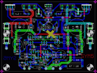
Keen , I see PMA's line of thought here, at least for this amp. The pulses here are right next to the sensitive parts of the amp (no distance) with only an R/C, (R31/C16) separating them from the input stage. No 1000uf cap here. In fact , they meet at the "X" .. the middle of the jumper (below- 1). Scoping an offset ground point of something like the symasym pcb will show the pulses , at least on something bigger with bigger caps.
Having bigger caps on the rails is nicer than having them offboard , so on a bigger board one could have 2 ground connects , one dirty ..one clean.
OS
Attachments
I will not use the 2200uF cap but do you recomend to use the BOM 1000uF or a lower value instead?
Thank you.
Regards,
Paulo.
Thank you.
Regards,
Paulo.
I will not use the 2200uF cap but do you recomend to use the BOM 1000uF or a lower value instead?
Thank you.
Regards,
Paulo.
You could test out both, nothing will explode. The only negative difference may be more hum, but I'm not sure. The only way to know is to try!
But if you don't have the time or the desire to experiment, I would use the 1000uF caps.
- keantoken
Dear moderators, i would ask you to change this thread's title
Because it is written in bad english....Explendid is not a correct word.
so, if possible, replace the title by:
"An amplifier designed by MikeB, the Symasym"
or
"Symasym, an amplifier designed by MikeB"
Please, choice the most perfect title considering english language (i am no good to decide that)
Symassym is now as days a brand, very famous in our forum, and people search using this name... a good idea to include it i think.... but i am not sure if Symasym is correctly typed.
Thanks in advance by your kindness.
regards,
Carlos
Last edited:
Carlos, I don't think that is a good idea after 3700 posts. It will confuse people. They will think it is a different thread.
Also "Explendid" sounds like "Extra Splendid" I thought you were just being clever 😉
BUT it would be nice to get "Symasym" in the title somehow.. I'll talk to Jason..
BUT it would be nice to get "Symasym" in the title somehow.. I'll talk to Jason..
Last edited:
- Home
- Amplifiers
- Solid State
- Explendid amplifier designed by Michael Bittner, our MikeB