Can you recommend a good link on this topic?
Thanks,
- keantoken
Yes, but original ONSemi link does not work, so try this link:
http://www.elenota.pl/d.php?pid=41512&pdf=an1308-d
Can I use MJL21193/4 for outputs? What would be the values for C14 and R31/32 in this case? Any other changes needed?
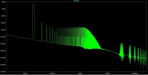
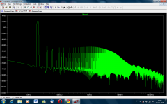
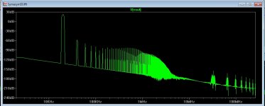
I have been simulating the SymAsym with these output transistors and the FFT pattern looks strange... Oscilation?
Thanks.
Regards,
Paulo.
I have been simulating the SymAsym with these output transistors and the FFT pattern looks strange... Oscilation?
Thanks.
Regards,
Paulo.
Attachments
Hi,
changing the output devices from the original to a close relative set in place a long re-compensation to get the copy to work well.
Changing to these completely different devices effectively creates a new amplifier. It will need to be compensated.
changing the output devices from the original to a close relative set in place a long re-compensation to get the copy to work well.
Changing to these completely different devices effectively creates a new amplifier. It will need to be compensated.
I can't tell you, I'm not a simulator user.
I have read many times that ONsemi's models of it's output devices are bad.
Have you read the original Symasym paper and the copied version? Was it Roender?
I have read many times that ONsemi's models of it's output devices are bad.
Have you read the original Symasym paper and the copied version? Was it Roender?
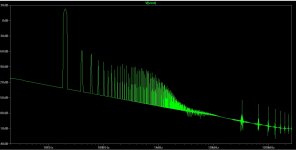
Is it possible your graphs were caused by bad bias adjustment? And your last FFT shows fundamental (20KHz?) at -80db? This is far less than listening volume and distortion is quite large, even if mainly lower order.
Your first graph actually looks normal to me. The blips at 30MHz and beyond are probably digital errors from using more FFT points than the simulation contains. Have you seen my signature?
- keantoken
Your first graph actually looks normal to me. The blips at 30MHz and beyond are probably digital errors from using more FFT points than the simulation contains. Have you seen my signature?
- keantoken
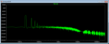
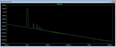
This is what I get now: THD 1kHz = 0.004503%; THD 20kHz = 0.009347%.
Bias is set at 53mA (higher bias values resulted in more distortion); Vin = 0.5V;
MJL21193/94 outputs.
Is this ok?
[QUOTEHave you seen my signature?][/QUOTE]
Yes, I'm learning LTSpice from your wiki. 🙂 Thanks!
Regards,
Paulo.
Bias is set at 53mA (higher bias values resulted in more distortion); Vin = 0.5V;
MJL21193/94 outputs.
Is this ok?
[QUOTEHave you seen my signature?][/QUOTE]
Yes, I'm learning LTSpice from your wiki. 🙂 Thanks!
Regards,
Paulo.
Attachments
HF distortion will be worse because of the slowness of the 21194/3 devices. Also remember the simulated quality of the amp is affected by the quality of the models.
Increasing VAS current may help, if you have not already. Have you messed with the stability compensation any? It will affect HF distortion.
- keantoken
Increasing VAS current may help, if you have not already. Have you messed with the stability compensation any? It will affect HF distortion.
- keantoken
I' tried different values for the compsensation cap and resistor but without much
success.
How do I increase VAS current?
success.
How do I increase VAS current?
Wait, have you seen this page? It has good models of the MJL3281a/0281a devices provided by Andy_C. Also has the 2SC4793/A1831 devices, very good drivers.
Transistors - diyAudio
It's hard to find on the WIKI, I should fix that...
- keantoken
Transistors - diyAudio
It's hard to find on the WIKI, I should fix that...
- keantoken
Let's have a reference schematic... You can increase the VAS current by decreasing R10.
- keantoken
I downloaded the models from ON Semi. I'll try these, thanks. Do you know a better model for 21193/94?
Increasing VAS current will also increase output bias current. Did you reset it?
If I knew of any more good DIY models I would have put them on that page. Making models takes time and patience, and we usually have other things we want to do.
- keantoken
If I knew of any more good DIY models I would have put them on that page. Making models takes time and patience, and we usually have other things we want to do.
- keantoken
I would expect the output bias to change very little if at all when changing the VAS current.Increasing VAS current will also increase output bias current. Did you reset it?
If the D.Self Vbe multiplier extra resistor is implemented, then you can tune out bias voltage changes with small VAS current changes.
The Vbe multiplier is not perfect, and I know this because I try to compare AB amps on equal grounds and watch the bias visually. The bias has a large effect on the harmonic profile, and 10 more mA of VAS current will definitely change this, possibly depending on the Hfe of the Vbe multiplier transistor.
Interesting about the Self multiplier, I didn't understand it before.
- keantoken
Interesting about the Self multiplier, I didn't understand it before.
- keantoken
- Home
- Amplifiers
- Solid State
- Explendid amplifier designed by Michael Bittner, our MikeB