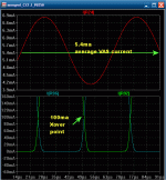
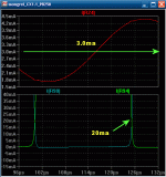
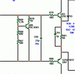
I would expect the output bias to change very little if at all when changing the VAS current.
If the D.Self Vbe multiplier extra resistor is implemented, then you can tune out bias voltage changes with small VAS current changes.
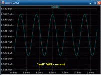
It DOES change , even with the extra resistor. The change is only dependent on the average VAS current , as the E-C decoupling cap's time constant will smooth out any changes that happen quickly (an audio signal). SEE BELOW...
(same amp at 5.4 and 3ma)
OS
Attachments
Hi,
Yes, the VAS current does change. It swings either side of quiescent bias due to it passing the audio signal to the next stage. Just as your post shows.
But from there on I disagree.
I'll use the slightly simpler case of a single pnp VAS transistor loaded with a CCS.
Set the CCS to 5.4mA, to match your first example.
The current flowing through the VAS ends up flowing through the CCS. Well not quite, that equality requires the base currents of the upper and lower drivers to be exactly equal and opposite. For the time being I will make that assumption and further assume the base currents are +1mA and -1mA to keep the drivers conducting their own bias currents.
The CCS current = VAS current = 5.4mA
The quiescent VAS bias current has to flow from top to bottom, but has 3 routes to get there. Through the bypass capacitor, well excluding leakage there is no DC current flowing this route.
That leaves the Vbe transistor collector and the string of resistors around the npn Vbe transistor.
Let's assume that 1mA passes through the first of the string of resistors. That leaves 3.4mA passing into the collector of the Vbe transistor.
Let's now look at the AC situation with VAS current varying to match the signal.
When the VAS current increases above 5.4mA, the extra has to go somewhere.
The bypass cap tries to hold a constant voltage across itself and so the amount of AC current through this route is tiny.
The Vbe transistor actively tries to hold a constant voltage from C to E. Again the change in voltage is tiny and as a result the change in current is tiny.
The resistor string can pass more current, but because the bypass cap and the Vbe transistor are trying to hold constant voltage across the resistor string the current change through the resistor string is tiny.
Heck, where does the increase in VAS current go?
It goes into the base of the upper driver transistor. This opens the driver to pass more current from C to E and that in turn lifts the output voltage of the driver to try to match the increase in VAS output voltage.
The upper driver will have a slightly higher Vbe and this increase is given up by the lower driver whose Vbe goes down slightly and turns the lower driver down slightly.
Similarly when the VAS reduces it's passing current below the quiescent 5.4mA, the main route for the change in current is through the bases of the drivers.
The lower driver is forced to pass more base current to the CCS because it is still demanding it's 5.4mA. As a consequence the lower driver turns on more and the upper driver turns off more.
Let's suppose the AC varies the 5.4mA by +-2mApk.
The VAS range of current is 3.4mA to 7.4mA.
Most of that variation passes through the bases of the drivers.
I would expect your simulator to show just how much. I would also expect your simulator to confirm the changes in current of the Bypass cap, of the Vbe transistir collector and the first resistor of the string.
I would not be surprised if you report a result showing more than 90% of the 2mApk current change goes through the driver bases.
That would leave a variation in Vbe current (the 3 routes) of <0.2mA.
Now back to what I said:
Now go back and individually remove the assumptions I made to make the analysis simpler. You will find that:
Non matching driver base currents have little effect on the change in Vbe current.
You will find that the CCS variation under dynamic loading makes little difference to the Vbe current.
You will find that replacing the CCS with a bootstrapped resistor pair makes little difference, but a bit more than a good CCS.
You will find that the AC current through the bypass cap and through the resistor string makes little difference.
I do hope I have this right.
I await your simulations.
The effect shown in the simulation is the swapping of the Vbe changes between the two drivers and the output devices as they alternately turn off and on more or less, not quite balancing out. This is not due to Vbe multiplier voltage change nor to Vbe current changes. It is due to the nature of the Vbe vs Ic curve of the output and driver devices
Yes, the VAS current does change. It swings either side of quiescent bias due to it passing the audio signal to the next stage. Just as your post shows.
But from there on I disagree.
I'll use the slightly simpler case of a single pnp VAS transistor loaded with a CCS.
Set the CCS to 5.4mA, to match your first example.
The current flowing through the VAS ends up flowing through the CCS. Well not quite, that equality requires the base currents of the upper and lower drivers to be exactly equal and opposite. For the time being I will make that assumption and further assume the base currents are +1mA and -1mA to keep the drivers conducting their own bias currents.
The CCS current = VAS current = 5.4mA
The quiescent VAS bias current has to flow from top to bottom, but has 3 routes to get there. Through the bypass capacitor, well excluding leakage there is no DC current flowing this route.
That leaves the Vbe transistor collector and the string of resistors around the npn Vbe transistor.
Let's assume that 1mA passes through the first of the string of resistors. That leaves 3.4mA passing into the collector of the Vbe transistor.
Let's now look at the AC situation with VAS current varying to match the signal.
When the VAS current increases above 5.4mA, the extra has to go somewhere.
The bypass cap tries to hold a constant voltage across itself and so the amount of AC current through this route is tiny.
The Vbe transistor actively tries to hold a constant voltage from C to E. Again the change in voltage is tiny and as a result the change in current is tiny.
The resistor string can pass more current, but because the bypass cap and the Vbe transistor are trying to hold constant voltage across the resistor string the current change through the resistor string is tiny.
Heck, where does the increase in VAS current go?
It goes into the base of the upper driver transistor. This opens the driver to pass more current from C to E and that in turn lifts the output voltage of the driver to try to match the increase in VAS output voltage.
The upper driver will have a slightly higher Vbe and this increase is given up by the lower driver whose Vbe goes down slightly and turns the lower driver down slightly.
Similarly when the VAS reduces it's passing current below the quiescent 5.4mA, the main route for the change in current is through the bases of the drivers.
The lower driver is forced to pass more base current to the CCS because it is still demanding it's 5.4mA. As a consequence the lower driver turns on more and the upper driver turns off more.
Let's suppose the AC varies the 5.4mA by +-2mApk.
The VAS range of current is 3.4mA to 7.4mA.
Most of that variation passes through the bases of the drivers.
I would expect your simulator to show just how much. I would also expect your simulator to confirm the changes in current of the Bypass cap, of the Vbe transistir collector and the first resistor of the string.
I would not be surprised if you report a result showing more than 90% of the 2mApk current change goes through the driver bases.
That would leave a variation in Vbe current (the 3 routes) of <0.2mA.
Now back to what I said:
Is 0.2mA variation cf 5.4mA quiescent bias within the definition of small change?you can tune out bias voltage changes with small VAS current changes
Now go back and individually remove the assumptions I made to make the analysis simpler. You will find that:
Non matching driver base currents have little effect on the change in Vbe current.
You will find that the CCS variation under dynamic loading makes little difference to the Vbe current.
You will find that replacing the CCS with a bootstrapped resistor pair makes little difference, but a bit more than a good CCS.
You will find that the AC current through the bypass cap and through the resistor string makes little difference.
I do hope I have this right.
I await your simulations.
The effect shown in the simulation is the swapping of the Vbe changes between the two drivers and the output devices as they alternately turn off and on more or less, not quite balancing out. This is not due to Vbe multiplier voltage change nor to Vbe current changes. It is due to the nature of the Vbe vs Ic curve of the output and driver devices
Last edited:
by Andrew T. - Let's suppose the AC varies the 5.4mA by +-2mApk.
The VAS range of current is 3.4mA to 7.4mA.
Most of that variation passes through the bases of the drivers.
I would expect your simulator to show just how much. I would also expect your simulator to confirm the changes in current of the Bypass cap, of the Vbe transistir collector and the first resistor of the string.
I would not be surprised if you report a result showing more than 90% of the 2mApk current change goes through the driver bases.
That would leave a variation in Vbe current (the 3 routes) of <0.2mA.
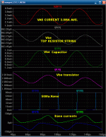
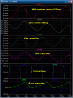
I see that the driver bases and their effect on VAS/Vbe currents are not a factor. This was done on the symasyms "big brother" (CX1.1) with a standard "self" Vbe multiplier (pix-3). As can be seen on comparison of the 2 compound plots (pix 1,2) the "change" is in the Vbe transistor and it's resistive divider. This corresponds to the Xover change (50ma to 190ma). Absolutely confirmed on the real-world version.
This amp is a little different than a standard "self" amp in its interaction with the Vbe , as the "self" has a fixed steady state CCS at the negative rail (pix 4 -VAS Current) with less than a uA of fluctuation.
Anyways , look for yourself...
OS
Attachments
I was not talking about Vbe multiplier voltage modulating in realtime, I was only pointing out that if you increase the quiescent current, you will have to reset the output bias current to the way it was before. Try it. Make a Vbe multiplier, run 5mA through it, then run 10mA through it and measure the voltage difference, maybe even calculate the effective resistance.
Because the Vbe mtuliplier is a voltage source, it absorbs transverse currents from the driver Ib's and whatever else would attempt to change bias voltage. However unaided it does have an impedance, like 75 ohms I think? I dunno if I ever measured it but mA do matter, even an increase in 1mA quiescent will affect the crossover distortion. Unlike in a Blameless, the balanced VAS of the Symasym helps ensure that little current flows through the multiplier, not to mention the help of the decoupling capacitor. So footprint at AC is small.
- keantoken
In this respect, diodes are still a good solution.
For a classical dual emitter follower, as in Ostripper
amp , i use five BYW80/200 in isowatt insulated package.
One diode is paraleled with a resistor to set the quiescent
current.
This arrangement has the advantage of slightly overcompensating
the output stage.
Quiescent current generally increase no more than 20% from
25 to 70° , assuming the VAS current doesn t move more than 10%
in the same temp range.
Hi Os,
thank for running all those simulations.
One fact that does surprise me is just how much of the VAS current variation passes through the bypass cap. Well that's the way I read the data.
The self Vbe is wired up wrong.
The cap has to go on the other side of the multiplier. It connects the VAS output directly to the tail CCS.
The tapping to the upper driver comes from the collector of the Vbe not the top of the extra resistor.
I have started working with LT in another thread. My, I am a slow learner.
I'll see what I can do with your spice lists.
I'll see if I can work out how to plot the voltage variation across the Vbe and the cap.
this sounds like undercompensation.slightly overcompensating
the output stage.
Quiescent current generally increase no more than 20% from
25 to 70° , assuming the VAS current doesn t move more than 10%
in the same temp range.
Hi Os,
The self Vbe is wired up wrong.
Ya got me... 😀😀 (below) MY cap on the wrong side of the collector resistor. 🙁
OS
Attachments
Last edited:
Ya got me... 😀😀 (below) MY cap on the wrong side of the collector resistor. 🙁
OS
Also R79 is also connected to the wrong side of R70. 😀 Very NAIM clone of you.
this sounds like undercompensation.
Right, but as specified, only if the VAS current increase
with temperature.
Otherwise, it s overcompensating....
Hi,
I have some Muse 2200uF, could I use them for C12/13 instead of 1000uF?
Thanks,
Paulo.
Any extra filtering on the rails is a good thing. It shouldn't affect operation negatively.
- keantoken
I awoke three or four times this morning thinking about the bypass cap current.
There is something I am not understanding.
Why is there current through the bypass cap when the VAS is modulating?
Told you, I'm not good at AC circuit theory.
There is something I am not understanding.
Why is there current through the bypass cap when the VAS is modulating?
Told you, I'm not good at AC circuit theory.
For a cap to work, there must be a voltage change across it. So you see there is no way a capacitor can possibly filter anything completely. A capacitor cannot totally absorb any load.
The cap and multiplier share the load (load being the current they will absorb as their effective impedance allows). Say the Vbe multiplier has a 220 ohm impedance. The 22uF bypass cap has high impedance at low frequencies, which decreases at several db per octave. At say 1khz the cap still has fairly high impedance, if it is equal to the multiplier's the load will be shared equally, except at harmonics of the fundamental where the cap has lower effective impedance due to the frequency.
Hope this helps,
- keantoken
Any extra filtering on the rails is a good thing. It shouldn't affect operation negatively.
- keantoken
There is an exception - if you put a high value cap on the amp PCB, and it is supplied by unregulated voltage with ripple, then high impulse ripple current flows into the PCB ground and it can induce quite high noise (hum) voltage and worsen S/N.
Regards,
this is where I am getting left behind.For a cap to work, there must be a voltage change across it.
The Vbe multiplier keeps an almost constant DC voltage across the cap.
The cap itself has a very low impedance to audio frequencies.
The cap plates float up and down in sympathy with the signal coming from the VAS.
The multiplier does it's best to ensure the cap voltages, both DC and AC do not change. At low frequency where the cap impedance becomes significant then that LF impedance will allow an LF voltage to develop in sympathy with the VAS modulation.
Now this where I got lost.The posted data showed tiny current changes in the Vbe transistor collector and top resistor of the string. These tiny current changes confirmed to me that the voltage changes across the resistor string and the parallel Vbe transistor must be very small.
Why does the capacitor show current changes approximating to 1mA?
If the voltage across the capacitor changes by just a few uV, then surely the current should also be in the uA range.
Why not?
If the voltage across the capacitor changes by just a few uV, then surely the current should also be in the uA range.
Why not?
To change the voltage across a cap by a few uV
in a short time, the source must output a big current
to charge the cap in the said time....
Classical capacitors charging equations....
but we are not talking about a short time. We are dealing with audio signals and sinewave ones through a simulator.
but we are not talking about a short time. We are dealing with audio signals and sinewave ones through a simulator.
If there s a variation of voltage multiplier impedance or
a variation of the VAS current , there will be forcibly a
higher voltage across the voltage multiplier.
The rising voltage will charge the cap in a very short time
since it is INCLUDED in the feedback loop.
It is the amp s NFB that is correcting a moving DC
working point.
- Home
- Amplifiers
- Solid State
- Explendid amplifier designed by Michael Bittner, our MikeB
