jacco vermeulen said:Pavel means: not mounted straight.
OK.
They are mounted like that because of gaps between radiators racks. Look an the picture where bolts are.
And I do not have a threader... 🙁
I know its not perfect 😉 but thats my second ever, first "real" amp (first ever was chipamp
 )
)Hope its only aesthetic issue 🙂
You'll have to learn to appreciate Upupa.
He's making you do better on details next time, with a touch of humor and lots of vodka.
He's making you do better on details next time, with a touch of humor and lots of vodka.
kubedes said:
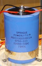
 What's the votage rating of the 22mF elyt cap ? If it's not at least 80v, don't start your amp again!!!!
It's amazing that your amp does play at all without any gnd connected. Likely that it has very weak bass.
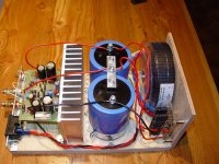
You have to rework your powersupply, you need 2 elyts in series, where the middle connection forms the ground and has to be connected to the ground output from the rectifier and the VGND connection on the amp board.
Mike
MikeB said:
As on pic above i've corrected PS.
Elyts are 50VDC, but they survived .

MikeB said:
It's amazing that your amp does play at all without any gnd connected. Likely that it has very weak bass.
Mike
That was just like you said.
Poor bass and "floating" sound
Thank you

--
Piotr
Attachments
Neat work, (now you have the PSU sorted)!
What's the rest of the encolsure going to look like?
What's the rest of the encolsure going to look like?
kubedes said:Corrected PS.
Now everything sounds fine.
Nice !
kubedes said:
As on pic above i've corrected PS.
Elyts are 50VDC, but they survived .
You were very lucky, a cap of that size exploding... ouch!
Mike
More interestingly,
how does one get sound with a ps-cap connected between the 2 rails ?
I can understand that the circuit could operate but where does the speaker return go to, or is that the top black wire that goes to the rect. bridge ?
Anyone care to enlighten the dysfunctional ?
Looks like a very close call, that blue thing seems to be a +30 years old.
pinkmouse said:
What's the rest of the encolsure going to look like?
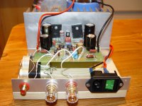
Size 16x16x35 cm (width x height x deep). Typical monoblock.
Front panel clean, few mm bigger (higher and wider) than rest of the case.
All aluminium 4 mm - naturally anodized. (I do not like black )
Power switch and diode indicating "operate" on top just behind front panel.
I have little time to design it precisely.
Yes, I was 😎MikeB said:
You were very lucky, a cap of that size exploding... ouch!
Mike
Hopefully it din't happen.
Thank you all for help, and comments 😉
jacco vermeulen said:More interestingly,
how does one get sound with a ps-cap connected between the 2 rails ?
I can understand that the circuit could operate but where does the speaker return go to, or is that the top black wire that goes to the rect. bridge ?
Anyone care to enlighten the dysfunctional ?
Looks like a very close call, that blue thing seems to be a +30 years old.
jacco
look at this picture. that posibbly clear that "black wire" problem.
Photo was taken in such angle that this two diffrent balck wires look like they're "connected "
That's coincident 😉
lower wire is "ground", upper is "negative"
I haven't found any info about those big blue caps
those are in mint condition, after swiching off amp is playing at least 4 seconds.
Friend of mine relaced PS caps with those Sprague in Jeff Rowland amp (can't remember which one) and the result was great.
Attachments
how does one get sound with a ps-cap connected between the 2 rails
Don't forget the 2x 1000uF decouplingcaps(bigger ones) on the pcb Jacco.
The black wire on the pcb is the minus voltage wire.
my 2 euro cents....
Loek
Don't forget the 2x 1000uF decouplingcaps(bigger ones) on the pcb Jacco.
The black wire on the pcb is the minus voltage wire.
my 2 euro cents....
Loek
Loek,
whenever you feel like it's time for something different, you can come stand beside me all day and slap me in the face every 15 minutes.
whenever you feel like it's time for something different, you can come stand beside me all day and slap me in the face every 15 minutes.
jacco vermeulen said:Loek, whenever you feel like it's time for something different, you can come stand beside me all day and slap me in the face every 15 minutes.

😀 😀 😀 😀 😀 😀 😀
oh, my stomache
😀 😀 😀
kubedes said:
jacco
look at this picture. that posibbly clear that "black wire" problem.
Photo was taken in such angle that this two diffrent balck wires look like they're "connected "
That's coincident 😉
lower wire is "ground", upper is "negative"
I haven't found any info about those big blue caps
those are in mint condition, after swiching off amp is playing at least 4 seconds.
Friend of mine relaced PS caps with those Sprague in Jeff Rowland amp (can't remember which one) and the result was great.
I know that this is likely not the final configuration, but I'd suggest one change: Orient the mains input vertically and move it all the way to the corner - away from the pcb. As it is, the mains wiring runs pretty close to your input signal paths and may induce some hum at mains frequency. You can experiment with this a little, by removing the mains switch/socket from the frame and moving it around carefully while powered up and listening for hum on the outputs. Also, put a nice tight twist on the mains wiring.
Sheldon
slap me in the face every 15 minutes.
Hi Jacco, in stead of slapping i better could give you a kiss because you are a nice guy in my opinion.
I will make you a nice salsa CD compilation for a (late) Xmas present and maybe then for you it's time for something different...
Have a nice Xmas you all and good luck.
Loek
Hi Jacco, in stead of slapping i better could give you a kiss because you are a nice guy in my opinion.
I will make you a nice salsa CD compilation for a (late) Xmas present and maybe then for you it's time for something different...
Have a nice Xmas you all and good luck.
Loek
SELL new 2 x SymAsym v5.2 Power Amp
I have to sell:
2x SymAsym v5.2 Power Amp and some pre-driver and driver BJTs
See all info: http://www.diyaudio.com/forums/showthread.php?s=&threadid=92887
I have to sell:
2x SymAsym v5.2 Power Amp and some pre-driver and driver BJTs
An externally hosted image should be here but it was not working when we last tested it.
See all info: http://www.diyaudio.com/forums/showthread.php?s=&threadid=92887
Hello MikeB,
What do you think about this design?
http://www.diyaudio.com/forums/showthread.php?postid=1101182#post1101182
Best regards,
Mihai
What do you think about this design?
http://www.diyaudio.com/forums/showthread.php?postid=1101182#post1101182
Best regards,
Mihai
Hi Mike,
I made the second Syamasym,
This time dual mono -/+39,7V idle 150mA, trafos 150W,
As input trans I used 2SK30GR, and I drunk beers after the work (great sacrifice
 ).
).
I had only 6 trans so matching was done only right for one pair 5,33/5,45mA. The second was 5,13mA/3,49mA of Idss, so it was asymmetric.
Final impressions are better than for 2SK170 but the asymmetric pair gave +623mV at the output. Better pair gave +44mV at the output.
As output trans I used MJL2193/4 which you advised as „sweet” what they were indeed.
I cannot stop thinking about my general concept, that only non-complicated amplifiers are good sounding (see my TCJ projects). Your design spoiled this “good” idea.
I made the second Syamasym,
This time dual mono -/+39,7V idle 150mA, trafos 150W,
As input trans I used 2SK30GR, and I drunk beers after the work
(great sacrifice ).I had only 6 trans so matching was done only right for one pair 5,33/5,45mA. The second was 5,13mA/3,49mA of Idss, so it was asymmetric.
Final impressions are better than for 2SK170 but the asymmetric pair gave +623mV at the output. Better pair gave +44mV at the output.
As output trans I used MJL2193/4 which you advised as „sweet” what they were indeed.
I cannot stop thinking about my general concept, that only non-complicated amplifiers are good sounding (see my TCJ projects). Your design spoiled this “good” idea.
padamiecki said:Hi Mike,
I made the second Syamasym,
This time dual mono -/+39,7V idle 150mA, trafos 150W,
As input trans I used 2SK30GR, and I drunk beers after the work
I had only 6 trans so matching was done only right for one pair 5,33/5,45mA. The second was 5,13mA/3,49mA of Idss, so it was asymmetric.
Final impressions are better than for 2SK170 but the asymmetric pair gave +623mV at the output. Better pair gave +44mV at the output.
As output trans I used MJL2193/4 which you advised as „sweet” what they were indeed.
I cannot stop thinking about my general concept, that only non-complicated amplifiers are good sounding (see my TCJ projects). Your design spoiled this “good” idea.
Padamiecki, nice to hear that you like symasym. 🙂
Hmm, i always thought of symasym beeing non-complicated... 😉
Sorry to have spoiled your "good" idea. 😀
Mike
- Home
- Amplifiers
- Solid State
- Explendid amplifier designed by Michael Bittner, our MikeB