My only notes, that the load of the VAS, should stay on the VAS, and not on the output of the follower.
sajti
sajti
sajti said:My only notes, that the load of the VAS, should stay on the VAS, and not on the output of the follower.
sajti
Why? VAS buffering results in better voltage drive of output transistors, less VAS loading and lower sensitivity to imperfect matching of output transistors. Output transistors are non-linear impedance load for VAS.
I guess he means the r-loading to the vas. R-loading the buffer should not have any effect, as the output impedance of the buffer is already quite low.
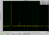
You can get rid of a very great amount of the unlinear load to the vas by closely matching the driver transistors. This removes the higher order even harmonics that were visible in measurings.
See attachment for version with matched drivers. (JFET-version with MJL0281/0302 as op devices) ~1W into 8ohm.
Mike
Attachments
"You can get rid of a very great amount of the unlinear load to the vas by closely matching the driver transistors"
very neat trick !
very neat trick !
MikeB said:I guess he means the r-loading to the vas. R-loading the buffer should not have any effect, as the output impedance of the buffer is already quite low.
You can get rid of a very great amount of the unlinear load to the vas by closely matching the driver transistors. This removes the higher order even harmonics that were visible in measurings.
See attachment for version with matched drivers. (JFET-version with MJL0281/0302 as op devices) ~1W into 8ohm.
Mike
Hi Mike,
You have right! I mean the R-load of the VAS. Your results looks quite nice!
sajti
Hi Mike,
I've always done this, even when servicing amplifiers. I knew that matching these parts made a difference but I never knew exactly why. I also did this when building the SymAsym.
Thank you sir.
-Chris
I've always done this, even when servicing amplifiers. I knew that matching these parts made a difference but I never knew exactly why. I also did this when building the SymAsym.
Thank you sir.
-Chris
MikeB said:
See attachment for version with matched drivers. (JFET-version with MJL0281/0302 as op devices) ~1W into 8ohm.
Mike
Hi Mike,
Where is the schematic of your JFET version ?
Which post if you already post it ?
thanks.
rgds,
G33/33
G33, it's not a special schematic, just 2sk170 instead of mpsa18 as input transistor. But, this is only possible if supply voltage is not above 36v.
Mike
Mike
Hi MikeB,
How do you match drivers? I thought matching PNP to a NPN was difficult. Which parameters?
Are you saying you just dropped in the 2SK170s without any further adjustments?
thanks
How do you match drivers? I thought matching PNP to a NPN was difficult. Which parameters?
Are you saying you just dropped in the 2SK170s without any further adjustments?
thanks
Greg Erskine said:Hi MikeB,
How do you match drivers? I thought matching PNP to a NPN was difficult. Which parameters?
Are you saying you just dropped in the 2SK170s without any further adjustments?
thanks
Hi Greg, you only need to match for hfe. I have a small circuit with a ccs to measure hfe. You can also measure hfe of drivers inplace on the board by measuring the voltage across the 22ohm base stoppers.
Yes, the jfets are a direct drop in. As they have lower voltage gain, no adjustment is necessary.
Mike
Greg Erskine said:
Are you saying you just dropped in the 2SK170s without any further adjustments?
🙂
let me answer instead of Mike,
I used last 4 pieces from my stock of 2SK170s for the input of Symasym, two of them were almost identical,
but second pair was different (2,3mA vs 3,4mA of Idss).
Result: -4mV of the offset in right chanel.
but as better matching as lower offset.
MikeB said:
Yes, the jfets are a direct drop in. As they have lower voltage gain, no adjustment is necessary.
Mike
Thanks Mike,
Do you use 22 Ohm source resistor ? My sysmasim is low gain version that use 22 ohm emitter resistor at the input Tr.
rgds,
G33/33
Hi Mike,
I was under the impression that the degeneration resistors were not required with matched FETs. Have I got this wrong?
-Chris
I was under the impression that the degeneration resistors were not required with matched FETs. Have I got this wrong?
-Chris
Herr Bittner, i've sent you an email a few days ago, on your Synetic address, i'm not sure if you've received it / read it. If you've been (too) busy, i'll understand 🙂 I was just curious about the (possible) effects of a few component value changes in your Symasym.
If necesary, i'll gladly replicate the email contents here...
Thanks in advance
Chris
If necesary, i'll gladly replicate the email contents here...
Thanks in advance
Chris
Hi Chris,
Run it by the group and we can all learn.
Hi Mike,
I understand. Thanks. Still, may be okay if the FETs are well matched.
-Chris
Run it by the group and we can all learn.
Hi Mike,
I understand. Thanks. Still, may be okay if the FETs are well matched.
-Chris
"Back by public demand" 
Here's the contents of the aforementioned email...
--------
I have a few questions about the amplifier you
designed (mostly about the PCB/layout and a few
component choices).
I modified your layout, slightly. I elongated the
board a bit, on the top part (with the power
transistors), so the traces wouldn't be so cramped
together. I also put alternative holes for the 100n
caps on the supplies, for 10mm pitch, and a different
input cap (6,8u/63V ERO film cap, plus a 100n on the
back of the PCB) and I changed the fuse holders
(because i can recover that type of vertical fuse
holders). And now, the questions...
1) Would there be any problem / performance issue if i
used 470n caps instead of 100n, for supply decoupling?
I hope not..
2) I couldn't get my hands on any 47n/100V caps, for
the output Zobel network. What would be better to use,
100n or 33n? (the only values at higher voltages i have - 100-160-250V)
3) What would the consequence of changing the value of
the "speedup capacitor" between the driver emitters,
up or down? (33n, 470n, 1u) Any possible improvement?
3) I can't find mica caps, for the small values. Will
Wima FKP2-series do for the 100p and 330p, and an NPO ceramic for the 10p?
-------
Chris
Hi Chris,
My take on it .....
1. No, they will be fine.
2. Try 100 nF. Should be okay.
3. The type of cap is more important than the exact value. You can try this at different frequencies while watching the distortion.
4. Mica or polystyrene (or polyprop) would be preferred. You may be able to make your 10 pF cap. Twist some CAT-5 internal wire together. Measure it as you trim off the end. I used mica for this one. (Thanks Mike).
I'm sure Mike or Pavel may disagree with me on something. Please do!
-Chris 😉
- Home
- Amplifiers
- Solid State
- Explendid amplifier designed by Michael Bittner, our MikeB