anatech said:
G33, keep the 22ohm resistors.
Mike
Hi Mike,
I understand. Thanks. Still, may be okay if the FETs are well matched.
-Chris
Thanks Mike.
Hi Chris,
Does it means that if I don't use 22 Ohm Source resistor I can use unmatched jfets ? say the difference of Idds is about 1 ma ?
rgds,
G33
Hi G33,
I have one hard rule on amplifiers. Match the parts or don't build it. I tend to match the diff pair transistors very tightly, then proceed to match all other pairs and complimentary devices. This only costs you time and a few extra parts, but the rewards are great.
Also, I'm asking Mike for my own clarification. In no way do I want to contradict him on his design.
So, for right now, match your transistors and use the 22R resistors. Or was it 33R he mentioned?
-Chris
Hi Chris,
do the parts that matched in the circuit, stay pretty much matched throughout their life ? 5 yrs - 7 years ?
Hartono
do the parts that matched in the circuit, stay pretty much matched throughout their life ? 5 yrs - 7 years ?
Hartono
Hi Hartono,
Yes they do, unless they are stressed due to an electrical fault or excessive temperatures. After many years they may drift apart, but we are talking 20 + years.
Often when I get a blown amp in for service, the diff pair on the affected channel is no longer balanced because one of the junctions went into reverse breakdown. I have seen a couple that where noisy and a few that failed outright. Not all the time, but enough so that I automatically check there.
-Chris
If I have 40v,can R31 and R32 be adjusted so the voltage is 36v at theG33, it's not a special schematic, just 2sk170 instead of mpsa18 as input transistor. But, this is only possible if supply voltage is not above 36v.
pre stage?
Ryssen said:
If I have 40v,can R31 and R32 be adjusted so the voltage is 36v at the
pre stage?
R31 and R32 are used as part of a RC filter for the rails. Their intended role is not for dropping voltage.
Hi Ryssen,
You could use a cascode pair to lock the drain voltage at some lower value, say about 10 VDC source - drain. This would have a number of positive effects. The distortion should be reduced as a side effect.
-Chris
Edit: I should expand on my two letter answer. You could drop the voltage and even regulate it lower. The result would be wasted dissipation in the output stage for nothing as you just reduced the power output. The voltage amp can only generate drive up to the supply rails less a few volts each way.
No.If I have 40v,can R31 and R32 be adjusted so the voltage is 36v at the pre stage?
You could use a cascode pair to lock the drain voltage at some lower value, say about 10 VDC source - drain. This would have a number of positive effects. The distortion should be reduced as a side effect.
-Chris
Edit: I should expand on my two letter answer. You could drop the voltage and even regulate it lower. The result would be wasted dissipation in the output stage for nothing as you just reduced the power output. The voltage amp can only generate drive up to the supply rails less a few volts each way.
Ok,not the way to go then.The result would be wasted dissipation in the output stage for nothing as you just reduced the power output. The voltage amp can only generate drive up to the supply rails less a few volts each
Would a 2SK117 be an option?It can take some more voltage than 2Sk170.
If not then this is the way then...
I mean without J3,as the original schema.
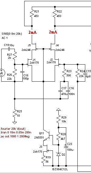
Maybe use 2sk 389 (LSK389)in cascode?
Hi Ryssen,
What you have shown is a cascoded pair. 2SK170 would be fine there, add a Zener to allow more D-S voltage. You could use bipolar transistors for J4&5 with the appropriate circuit changes.
-Chris
What you have shown is a cascoded pair. 2SK170 would be fine there, add a Zener to allow more D-S voltage. You could use bipolar transistors for J4&5 with the appropriate circuit changes.
-Chris
Ok,10volts zener,like you mentioned before?add a Zener to allow more D-S voltage. You could use bipolar transistors for J4&5 with the appropriate circuit changes.
Will there be any benefits if I use bipolar for J4,J5,compared to J-fets?
Hi Ryssen,
I am more comfortable with BJTs in this position. Jfet transistors will not give as defined a voltage here. Having said that, some people may get them to work. I would want to nail the drain voltage right down so we don't have any secondary drain - source voltage dependent variations.
-Chris
I am more comfortable with BJTs in this position. Jfet transistors will not give as defined a voltage here. Having said that, some people may get them to work. I would want to nail the drain voltage right down so we don't have any secondary drain - source voltage dependent variations.
-Chris
matching drivers.
Hi Mike,
I'am currently matching the output devices 2sc5200 2sa1943 and drivers 1530 1531.
I bought a smal lot of 25 pcs of each and i'apply constant current of 2ma for Ibe and 20v for Vce. I' get big difference between mje1530 and 1531 respectively beta of 330 and 550 .The output devices are more closely 2SC5200 beta 250 2Sa1943 350.
Does I'need to buy some more to get more close value of beta?
Many thanks ...JCB
Hi,
if you must match hFE then you should hold Ic constant and measure the variable Ib. That is not usually the way that DMM transistor testers work and why DMM give misleading results.
However, if you are testing output devices for parallel pairs it is more important to match Vbe for the same Ic or Ie.
Think about the operating conditions when the driver sends a voltage to the output bases. Each base sees the same voltage. Each emitter resistor is tied to the same voltage (the output line). The voltage across Vbe + Re is identical for each paralleled output device. If one wants identical currents to flow in each then the Vre drop must be the same and that means the Vbe must be the same.
Match Vbe arcoss the paralleled sets.
Replace mje15030/15031 with mje15034/15035 if you want to match by hfe/vbe ...
And mjw0281/0302 as finals insead of 2sa1943/2sc5200, hfe factory matched in 10%
And mjw0281/0302 as finals insead of 2sa1943/2sc5200, hfe factory matched in 10%
matching drivers
Thanks for youre reply AndrewT and roender.
I'use only one pair of output transistor by amplifier with Pavel modifications.
I'will try to get mje15034/15035 and keep the toshiba devices at output .And next try 2sk 170 in input and chek sonics differences..
Thanks for youre reply AndrewT and roender.
I'use only one pair of output transistor by amplifier with Pavel modifications.
I'will try to get mje15034/15035 and keep the toshiba devices at output .And next try 2sk 170 in input and chek sonics differences..
About sk170, only try this change if your supply voltage is not larger than 36v. sk170 has a max rating of 40v.
Mike
Mike
Start to build
I’m going to build 8 SymAsym for use in my active System as replacement for LM3886 gainclon-AMPs. (Parts already ordered.) The gainclons-AMPSs didn’t satisfy me at last. (no realistic bass)
I intend to use some Sanken 2SA1170 and 2SC2774 for the output stage. They are perfectly matched in pairs by Roederstein. I bought a huge amount 20 years ago for a DIY Project.
I was very pleased with the result, but the WAF wasn’t 10 years later not accepted and I have to use a “normal” System.
I checked the hole group in the last days and there are some questions left.
Witch board design shall I use? The original 5.3 or the H.B. version which is nice smaller. And why are there 2 groundpins at the H.B. version? Is there any known difference in the measurements between the boards or sound they different.
I don’t want use the coil-resistor and the resistor/capacitor devices at the output. It brings the output more in the middle of the board. Maybe less noise coupling between input/output.
For the first tests I will use the existing transformers +- 18V. I t should work.
Welcome to the club!
Yes, WAF can often be a problem...
I don't know these Sanken devices, do you have specs/sheets?
About PCBs, the H.B. version seems to work, there is one prototype working at the moment (single sided). I don't know if they sound different or behave different.
The symasym5.3 board is proven and the one H.B. built for testing.
Under no circumstances skip the resistor/capacitor devices at the output, they are mandatory und MUST be kept. The coil/resistor thing might be skipped, but i do not recommend skipping it.
Unless you use >100db efficient speakers, noise is no issue here. On my 90db speakers noise is not audible.
The +/-18v transformer is no problem.
Mike
It's funny, because many people have been reporting that LM3886 amps don't have a good bass, and I've built myself two of them that really didn't have bass. But recently I've built one that have a great Bass, and I switched it with Symasym, and I only noticed that Symasym is pretty more extended, despite the LM3886 (last build) have a very similar bass capabilities.
Both gainclones that didn't have bass were oscilating, it had a very false bass.
Althought is possible to build a Gainglone with strong bass, it sounds much more laid back, "shy", and trebles are too much smooth. Symasym is much more fun to listen, because of it's dynamics and you really listen the sound getting OUT from the box and filling the room.
Cheers !
- Home
- Amplifiers
- Solid State
- Explendid amplifier designed by Michael Bittner, our MikeB