
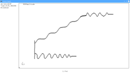
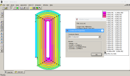
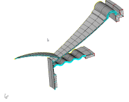
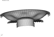
I use custom software. We have compared it regularly against COMSOL. What is custom about our software is the wrapper. We use FEMM4.2 for the magnetics, and Calculix and Z88 for different parts of simulating a cone or the spider.Do you have access to COMSOL?
A legitimate COMSOL license is prohibitive to pay for as a small company. We've been running our software since 2018 and designed nearly a hundred drivers since then. Our simulations come out very close to the real article. And we have save the butt of a few errant COMSOL designed drivers as well.
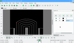
With a bunch of research to create our software we found some interesting information regarding simulations on the Opensource software versus COMSOL. With attention to the input details the answers are identical. The math behind the scenes to create the simulation is identical. The only difference is that FEMM 4.2 simulates in 3D but displays in 2D.
Attachments
-
 ca2.png13.9 KB · Views: 54
 -
 ca8.png93.3 KB · Views: 60
 -
 Comments on the surround drawing.png155.4 KB · Views: 52
 -
 ct3.png15.3 KB · Views: 59
 -
 dxf1.png59.9 KB · Views: 57
 -
 femm2.png62.5 KB · Views: 60
 -
 Screenshot_20170608_183229.png208.1 KB · Views: 60
 -
 Screenshot_20170608_183214.png290 KB · Views: 58
 -
 Screenshot_20190430_122501 cropped.png29.6 KB · Views: 54
 -
 Screenshot_20190430_122904 cropped.png65 KB · Views: 51
 -
 vcd_new_5.png106.6 KB · Views: 48
Well, if anyone else has already done a deep dive on the various ways of inductance demodulation eg. copper cap on the pole piece to make the voice coil inductance low and symmetric eg. original Philips drivers in the market by 1973, Ragnar Lian SD patent 1973-1993, vs 3 copper rings (Ragnar Lian’s patent for “SD-1” in 1994-2014), 2 copper rings eg. SEAS’ old Excel, vs 1-3 alu rings or 1-3 rings of variable resistivity eg 2 alu, 1 copper eg. KEF
And/or effects of current drive on them, I’d like to hear about…
And/or effects of current drive on them, I’d like to hear about…
Last edited:
Thank you for those measurements. I makes sense that if the motor is already really well demodulated, you are at the mercy of the nonlinearity of mechanical compliance at or below resonance, so current drive may make things worse. The is the infamous low damping factor for better control thing. With current drive there is no electrical damping at all and close to no motor force needed to get the driver to oscillate. The only thing that can improve it over the voltage driven scenario is MFB.@TNT
My hypothesis goes something like this-
A bare driver like an alu cone with a full copper sleeve eg. SB15/17 N(B)AC may not minimal to no real improvement.
I have the SB17NAC-04 here so one fine day...
b) A driver with one (or two) air cored inductor in series will show some improvement. The level of improvement may depend on the total series resistance and how much it linearizes the impedance.
I have the Scan-Speak 18W/8535 with the SD-1 (3 copper rings) as part of the ProAc Response 2.5 clone, with 3rd order low pass filters using 2 air core series inductors, so one fine day...
c) To linearize the response back to original response without the inductor. Why would one want to do that?
2.
@Kravchenko_Audio
Dear Mark,
I agree.
In theory, there is no difference between theory and practice. But in practice, there is.
( Benjamin Brewster)
Unfortunately I will not be able to do that experiment. That picture is an old one, after I had to repair a damaged driver. I've since reassembled it, and it's in a completed speaker now. I won't be disassembling it again.
Re: simulation vs observation-
That reminds of the time I wrote to @jackocleebrown at ASR
https://www.audiosciencereview.com/.../kef-r-meta-series-release.41420/post-1487851
asking why he didn't have a fully copper sleeve in the TOTL Reference/Blade META drivers ie. coax and woofers.
He was curious and wrote to me directly. We compared notes. With thanks @5th element
In the end we did not reach a consensus. But we stand by our research and I shared with him our findings*.
Hopefully we can look forward to the next generation KEF Reference/META UniQ transducers to have even lower distortion from the MF unit. (IMHO the HF is already top of the class. He did complete a PhD on Phase Plug Design for compression drivers and applied that knowledge when he went to work for Celestion, and KEF, both subsidiaries of (OEM battery giant) GP (Gold Peak))
Full disclosure: "*In the interest of transparency, we confirm that no financial compensation, funding, or material support was exchanged in relation to the research findings presented. All conclusions and interpretations are based solely on objective analysis, independent data assessment, and professional integrity. This disclosure underscores our commitment to unbiased inquiry and the ethical dissemination of information."
I am surprised that there is no benefit of current drive higher up in frequency. The Purifi folks seem to have done a really thorough job. There is a region between 100 and 200 Hz in what I suspect is the plot of 3rd harmonic (it is also labelled 2nd like the preceeding graph) where current drive seems better, but it is not systemetic, i.e. the same region in HD5 is worse, and in the midrange for both uneven HDs, current drive is identical or worse.
I would have expected uneven midrange to benefit from current drive even with the sophisticated motor. Now 20 R series resistance is only an approximation of current drive. Is there a chance you can use a larger resistance or acutally modify an amplifier for real current drive?
As for the SB15/17N..AC, they have a pretty good motor but their sleeve is not thick enough to be effective at LF, and there is no Neo magnet on the pole piece to saturate it. I bet they'll benefit from current drive.
I'm not sure I get what you are trying to tell us here:
"b) A driver with one (or two) air cored inductor in series will show some improvement. The level of improvement may depend on the total series resistance and how much it linearizes the impedance."
Do you mean that the series resistance of the inductors is already similar to current drive so there is little to be gained from full current drive?
@capslock
Good catch~ Your are correct in noticing the typo error in the 2nd graph again title "...2nd HARMONIC" is incorrectly labelled (the titles are manually entered by me), and that the legend in the bottom left, and the table in the top right corner stating 3rd harmonic is correct. Apologies.
There's little chance of me using a 40 ohm resistor because I would need to acquire some high power resistors. I could easily acquire 2x 80 ohm 10W resistors to run in parallel, but the power handling would unlikely to be sufficient.
No chance of the latter- at this stage my interest lies mainly in seeing what would happen if future all-in-one integrated manufacturers implement partial current drive in their products, or what happens with passive crossover networks...
Good catch~ Your are correct in noticing the typo error in the 2nd graph again title "...2nd HARMONIC" is incorrectly labelled (the titles are manually entered by me), and that the legend in the bottom left, and the table in the top right corner stating 3rd harmonic is correct. Apologies.
Currently I am using a 20 ohm cement wire wound resistor rated at 10Watts...Is there a chance you can use a larger resistance or actually modify an amplifier for real current drive?
There's little chance of me using a 40 ohm resistor because I would need to acquire some high power resistors. I could easily acquire 2x 80 ohm 10W resistors to run in parallel, but the power handling would unlikely to be sufficient.
No chance of the latter- at this stage my interest lies mainly in seeing what would happen if future all-in-one integrated manufacturers implement partial current drive in their products, or what happens with passive crossover networks...
Do we know of such examples...? Kii?all-in-one integrated manufacturers implement partial current drive in their products
//
Australian manufacturer SGR Audio:
https://www.sgraudio.com/collection/convex-series
Recently French manufacturer Focal:
https://www.focal.com/catalog/pro-audio/monitoring-speakers/utopia-main
there may others that am unaware…
https://www.sgraudio.com/collection/convex-series
Recently French manufacturer Focal:
https://www.focal.com/catalog/pro-audio/monitoring-speakers/utopia-main
there may others that am unaware…
So this resister is inductive already. Have you measured it's inductance?Currently I am using a 20 ohm cement wire wound resistor rated at 10Watts...
Have you validated this fear with measurements? My guess is that in a household listening environment and typical ~90dB @ 2.83V rated speakers, you could actually downgrade to 5W and they still would have a comfortable amount of overhead during normal listening levels.Currently I am using a 20 ohm cement wire wound resistor rated at 10Watts...
There's little chance of me using a 40 ohm resistor because I would need to acquire some high power resistors. I could easily acquire 2x 80 ohm 10W resistors to run in parallel, but the power handling would unlikely to be sufficient.
Of course, YMMV. If there's an exponential jump in living room space, a few more dB's may be required...
The difference between the “low inductive” wire wound cement resistor (<0.05 mH) and metal oxide film resistor with negligible inductance, at these frequencies, is within the margin of error.
Of course for real music it’s fine.
But in doing multiple exponential sine sweep measurements (mine last 12 seconds each round) with the 10W resistor in series, it goes get warm.
Of course for real music it’s fine.
But in doing multiple exponential sine sweep measurements (mine last 12 seconds each round) with the 10W resistor in series, it goes get warm.
You've probably already seen this, but Purifi has demonstrated reduced distortion with the PTT6.5X04-NAA-08 via increased drive impedance (series notch filter). The paper cone version does seem to have somewhat higher distortion overall through the midrange; perhaps motor nonlinearities don't dominate in that particular driver?Current drive seems to have no effect on the PTT6.5X04NFA.
I did a couple measurements of a woofer with a copper sleeve (buyout Tymphany AULA02014-0006) showing the effect of source impedance. The amp is a simple LM1875 chipamp with variable output impedance (originally designed for electric guitar use) and the mic is a cheap cardioid dynamic.
Low driving impedance (about 9Ω):

High driving impedance (about 70Ω):

These are with "Use harmonic frequency as ref" selected. Corresponding frequency responses (uncorrected; LF boost due to proximity effect):

Here's a photo of the pole piece, taken by Parts Express:

There seems certainly an improvement with the AULA02014-0006.
My hypothesis is now that the thickness of the copper sleeve may be factor.
To verify this, other drivers with thin copper sleeves could be tested eg. SB17NAC, MAN061.80


To be clear, we did not take apart these drivers
"for fun", or to "reverse engineer them"
It's one of those "here's what we prepared earlier"
And it all started because we started building our own coaxes when we couldn't find anything in the marketplace that was top flight true midrange coaxial.
Before we knew it, we're going on all kinds of side quests, like looking at
effect of cabinets on directivity,
distortion measurements - how accurate have they been, in the past,
the clear effect of microphone/signal chain on distortion measurement
hearing distortion not just measuring it
and now the effect of passive crossovers and current drive on distortion
and ...coming soon to a channel near you- the effect of spiders ...
Thanking @5th element and everyone else who's supported me on this journey- you know who you are.
My hypothesis is now that the thickness of the copper sleeve may be factor.
To verify this, other drivers with thin copper sleeves could be tested eg. SB17NAC, MAN061.80
To be clear, we did not take apart these drivers
"for fun", or to "reverse engineer them"
It's one of those "here's what we prepared earlier"
And it all started because we started building our own coaxes when we couldn't find anything in the marketplace that was top flight true midrange coaxial.
Before we knew it, we're going on all kinds of side quests, like looking at
effect of cabinets on directivity,
distortion measurements - how accurate have they been, in the past,
the clear effect of microphone/signal chain on distortion measurement
hearing distortion not just measuring it
and now the effect of passive crossovers and current drive on distortion
and ...coming soon to a channel near you- the effect of spiders ...
Thanking @5th element and everyone else who's supported me on this journey- you know who you are.
From what Steve has said he no longer has working software. He has been retired for the past 10 years. I on the other hand have freedom 85. Self employed most of my life. So no big pension. Plus I can't stop working! I'll go nuts!@mark: Take your time and then show us the Borresen too.
BTW: Is Steve Mowry no longer doing his own sims? I was under the impression the Steallus model range was his own work..
100% On a woofer anything less than 0.5mm is almost non-effective where you want the inductance compensation.My hypothesis is now that the thickness of the copper sleeve may be factor.
What is getting missed is that your motor design from the beginning will have a determining factor on your drivers distortion products.
I attached on paper that discusses this. There are a few more if you guys are interested.
High quality coaxial? If you want help you can drop me an email.And it all started because we started building our own coaxes when we couldn't find anything in the marketplace that was top flight true midrange coaxial.
Attachments
Seems probable to me. The sleeve in that driver seems thicker than most (from what I've seen), but still nothing like the Purifi woofers.My hypothesis is now that the thickness of the copper sleeve may be factor.
I also did some basic current distortion measurements which may be of some interest. These were done using the headphone output of a Behringer UMC1820 through a 100Ω 0.1% metal film resistor, so the drive level is fairly low.
2mH air core inductor (to show approx. measurement limits above ~200Hz):

AULA02014-0006:

Eminence Deltalite II 2512:

Old Eminence OEM 12" AlNiCo guitar speaker (model #52-8B, made in 1974):

Woofer from an old Definitive Technology ProMonitor 100 (simple shielded ferrite motor):

Celestion CDX1-1446 (ferrite HF compression driver):

Celestion CDX1-1747 (ferrite HF compression driver):

The 3rd through 5th harmonics in the AULA02014-0006 measurement have a low pass characteristic, which I'm guessing simply shows that the copper sleeve is more effective at higher frequencies. The Deltalite II 2512 has a neodymium slug magnet, but no shorting rings or sleeve (as far as I know).
It appears that the bigger magnet and higher flux density in the CDX1-1747 vs the CDX1-1446 makes a significant difference in the level of the odd harmonics, at least at this drive level.
Wow. That looks like a SB17 or SB15? Is the basket bolted to the top plate with screws rather than rivets? Can you get to them without damaging anything but the contact cement? One could add a more solid shorting ring or even a compensation coil there.There seems certainly an improvement with the AULA02014-0006.
My hypothesis is now that the thickness of the copper sleeve may be factor.
To verify this, other drivers with thin copper sleeves could be tested eg. SB17NAC, MAN061.80
View attachment 1456964
View attachment 1456966
To be clear, we did not take apart these drivers
"for fun", or to "reverse engineer them"
It's one of those "here's what we prepared earlier"
And it all started because we started building our own coaxes when we couldn't find anything in the marketplace that was top flight true midrange coaxial.
Before we knew it, we're going on all kinds of side quests, like looking at
effect of cabinets on directivity,
distortion measurements - how accurate have they been, in the past,
the clear effect of microphone/signal chain on distortion measurement
hearing distortion not just measuring it
and now the effect of passive crossovers and current drive on distortion
and ...coming soon to a channel near you- the effect of spiders ...
Thanking @5th element and everyone else who's supported me on this journey- you know who you are.
Same thing with the PPT, can you remove the basket simply by unscrewing it? Not that I'd know what to improve on that motor.
Lastly, I'm still in the dark as to what you meant by this:
"b) A driver with one (or two) air cored inductor in series will show some improvement. The level of improvement may depend on the total series resistance and how much it linearizes the impedance."
Thanks
The air core should not have current distortion unless it can vibrate mechanically or there is some iron nearby. Do you think this was the case or are we seeing the limitations of the amplifier? If so, why would it increase below 100 Hz?Seems probable to me. The sleeve in that driver seems thicker than most (from what I've seen), but still nothing like the Purifi woofers.
I also did some basic current distortion measurements which may be of some interest. These were done using the headphone output of a Behringer UMC1820 through a 100Ω 0.1% metal film resistor, so the drive level is fairly low.
2mH air core inductor (to show approx. measurement limits above ~200Hz):
View attachment 1456984
AULA02014-0006:
View attachment 1456985
Eminence Deltalite II 2512:
View attachment 1456986
Old Eminence OEM 12" AlNiCo guitar speaker (model #52-8B, made in 1974):
View attachment 1456987
Woofer from an old Definitive Technology ProMonitor 100 (simple shielded ferrite motor):
View attachment 1456988
Celestion CDX1-1446 (ferrite HF compression driver):
View attachment 1456991
Celestion CDX1-1747 (ferrite HF compression driver):
View attachment 1456992
The 3rd through 5th harmonics in the AULA02014-0006 measurement have a low pass characteristic, which I'm guessing simply shows that the copper sleeve is more effective at higher frequencies. The Deltalite II 2512 has a neodymium slug magnet, but no shorting rings or sleeve (as far as I know).
It appears that the bigger magnet and higher flux density in the CDX1-1747 vs the CDX1-1446 makes a significant difference in the level of the odd harmonics, at least at this drive level.
SB17
The first Philips and the 20 year old Mr. T are my friends, respectively.
Eric,
Without having to take apart (and reassemble) a transducer to inspect the motor (not recommended), I have a suspicion that the driver with the flattest impedance response benefits the LEAST from current drive.
Please see attachment.
Glad to be shown I'm wrong, so I can abort this investigation.
The first Philips and the 20 year old Mr. T are my friends, respectively.
A driver with one (or two) air cored inductor in series will show some improvement. The level of improvement may depend on the total series resistance and how much it linearizes the impedance."
Thanks
Eric,
Without having to take apart (and reassemble) a transducer to inspect the motor (not recommended), I have a suspicion that the driver with the flattest impedance response benefits the LEAST from current drive.
Please see attachment.
Glad to be shown I'm wrong, so I can abort this investigation.
Attachments
Last edited:
Generally, the less inductance a driver has, the more care was taken designing the motor, but it is not a 1:1 correlation. Inductance vs. excursion is one such giveaway, and it is pretty easy to measure. I still fails to see how this related to the two air coils in series.
Do the SB17 and the TTC have screws that you can get to without having to peel or cut off the spider?
Do the SB17 and the TTC have screws that you can get to without having to peel or cut off the spider?
- Home
- Loudspeakers
- Multi-Way
- Experiments with the current drive