Hello again, yes no problems I have many 430's and will experiment with one thats not that great ...so if something happens no loss LOL
anyways awaiting on the adding the pvf...
Lawrence
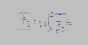
Hello Sk8Ter. I studied the schematic of hk 430, and came up with the attached proposed PVF scheme. Please note:
1. The 1 uF coupling cap from Vout to the 100 K PVF resistor. Without it, any DC offset at Vout is expected to be a problem. I recall that you had suggested in an earlier post using 56K instead of the [more cautious] 100K.
2. The base of the non-inverting bjt diff amp of power amp is an ideal point to inject PVF. Because the 1K input resistor has its other end terminating in the low output impedance of the preamp buffer; and/or like AC ground.
Tips: Start with the volume control at minimum, and select an FM station [mono rather than stereo] for later comparison at the loudspeakers.
1. The PVF connections are accessible on the amp board. Use the clips gizmo I showed in an earlier post to hookup. Connect the cap and the 100K resistor to a 3-terminal Euro connector, and then tuck'em safely in a plastic med bottle.
2. Hook up the PVF network before the amp is turned on. Otherwise one or more fuses will blow when done post turn on.
3. Push the loudspeaker switch on and measure DC offset without any load.
4. The load at the speaker terminals needs to be at this point 2 X-mas light bulbs connected in series; which have a net ~7 Ohm cold resistance. Both will blow if there's a malfunction or oscillation.
5. If all's well, connect 1 light bulb in series with a 4 -8 Ohm loudspeaker. Play some music at low level.
6. If all's well connect 2 light bulbs in parallel [1.5 Ohms cold], and connect the net light bulb fuse in series with the loudspeaker. Play some music at low volume.
7. Finally, connect the loudspeaker; preferably 8 Ohms to start.
8. Must repeat the above steps when the PVF resistor is lowered to a value less than 100 K. The risk of oscillation and blown fuses will rise quickly.
A comparative subjective assessment is now possible. The Balance knob turned fully clock/anti clockwise will be useful to compare the two channels with and without PVF. Listen for the relative level noise, and hum etc..
Hope all will go well.
Attachments
See Figure 4 on this page:
Variable Amplifier Impedance
Thank you for your 2 posts. The article in the above link is a must read for me. I fully agree with you that a light bulb sense resistor/fuse will encourage [your] interesting and fitting terminology of feedback runaway. I played loud music with both positive feedback loops engaged. The system did not experience this problem; which would have blown the light bulb fuse/sense resistor.
Hello Sk8Ter. I studied the schematic of hk 430, and came up with the attached proposed PVF scheme. Please note:
1. The 1 uF coupling cap from Vout to the 100 K PVF resistor. Without it, any DC offset at Vout is expected to be a problem. I recall that you had suggested in an earlier post using 56K instead of the [more cautious] 100K.
2. The base of the non-inverting bjt diff amp of power amp is an ideal point to inject PVF. Because the 1K input resistor has its other end terminating in the low output impedance of the preamp buffer; and/or like AC ground.
Tips: Start with the volume control at minimum, and select an FM station [mono rather than stereo] for later comparison at the loudspeakers.
1. The PVF connections are accessible on the amp board. Use the clips gizmo I showed in an earlier post to hookup. Connect the cap and the 100K resistor to a 3-terminal Euro connector, and then tuck'em safely in a plastic med bottle.
2. Hook up the PVF network before the amp is turned on. Otherwise one or more fuses will blow when done post turn on.
3. Push the loudspeaker switch on and measure DC offset without any load.
4. The load at the speaker terminals needs to be at this point 2 X-mas light bulbs connected in series; which have a net ~7 Ohm cold resistance. Both will blow if there's a malfunction or oscillation.
5. If all's well, connect 1 light bulb in series with a 4 -8 Ohm loudspeaker. Play some music at low level.
6. If all's well connect 2 light bulbs in parallel [1.5 Ohms cold], and connect the net light bulb fuse in series with the loudspeaker. Play some music at low volume.
7. Finally, connect the loudspeaker; preferably 8 Ohms to start.
8. Must repeat the above steps when the PVF resistor is lowered to a value less than 100 K. The risk of oscillation and blown fuses will rise quickly.
A comparative subjective assessment is now possible. The Balance knob turned fully clock/anti clockwise will be useful to compare the two channels with and without PVF. Listen for the relative level noise, and hum etc..
Hope all will go well.
Thanks I will give this a shot asap....some reservations...will the 1mf cap be enough? I mean will it limit low freq somehow??
Thanks so much!!!
Lawrence
It proves the only thing that really matters at the end of the day: "Do you like to listen to it?"
I don't enjoy my hifi with a distortion analyzer or an oscilloscope. I like to listen to music. If I enjoy music through my amp and speakers, I am happy.
🙂
Cheers,
Johannes
Missed the point. Did I say anything about measurements? I don't care if you think it sounds better, without a blind listening test many people imagine all kinds of changes in there sound, even when there is none. And if there really is a change, just because you think it sounds better dosnt mean others do. Lots of people prefer sound with more distortion. So knock your self out , and do what ever pleases your ear, but someone saying "it sounds better" with out testing means nothing to me.
Thanks I will give this a shot asap....some reservations...will the 1mf cap be enough? I mean will it limit low freq somehow??
Thanks so much!!!
Lawrence
Please take your time. May wish to start with a 4.7 or 10 uF instead which may have to be polarized. Thereafter increase slowly to a value which will not limit low frequency response.
US patent 4,899,387 is entitled Active Low Frequency Acoustic Resonance Suppressor; inventor Nelson S. Pass. It is a device which exemplifies the clever use of Positive Feedback to suppress and/or attenuate standing waves. Imagine an enclosed woofer [part of this device] which sits in the corner of a listening room, and is stimulated with bass from music. When sound pressure from standing waves [SW] push the woofer cone in [for example], the control power amplifier [part of this device] simultaneously causes this cone to continue moving in the same direction or being sucked in. This increased pressure by SW is attenuated with a vacuum or low pressure right at the cone surface.
A control power amp which uses Positive Current Feedback [PCF] is expected to be valuable in this app; because its PCF will target the performance of the above woofer in its low frequency range of operation where standing waves are also present.
A control power amp which uses Positive Current Feedback [PCF] is expected to be valuable in this app; because its PCF will target the performance of the above woofer in its low frequency range of operation where standing waves are also present.
I would love to see some electronic guru's design a schematic for the F6 using some positive feedback for us solder slingers to experiment with. Now that I have my M2 built I would love to play with the F6 circuit that uses negative feedback and introduce some positive. Nelson says it can be done with other amplifiers as well.
It is quite easy.
Just add a 0,5 ohm (or less value) power resistor between the speaker and ground. Use a small 100 ohm 2 watt potentiometer parallel over the 0,5 ohm resistor and couple the middle tap to the input of the Jensen transformer. With a transformer in the positive feedback loop I would be very careful and very very slowly increase the positive feedback. Remember to use fast fuses and have several matched pairs of spare output transistors at hand....
If trying this method I would like to have some kind of sacrificial loudspeaker connected to the amp, since it can get truly wild very fast...
Cheers,
Johannes.
Thanks Johannes, you are the first to suggest any way of adding positive current feedback to the F6. When you say "add a .5 ohm power resistor between speaker and ground" I assume you mean from the out point of the amplifier to ground.
If you are interested in a PCF version of F6 you should start a new thread.
I can post some simple schematics of where you can statrt with your experiments. Hopefully Nelson Pass will chime in. I would guess you need to limit the bandwidth of the PCF loop to avoid oscillation. The transformer with all its inductance and stray capacitance will make it unstable and prone to oscillation.
There are several ways to add PCF, so it is an interesting subject.
Cheers,
Johannes
Applications of Positive Voltage Feedback
I have two applications for Positive Voltage Feedback [PVF]. I refer you to the thread in this forum entitled Class aP amplification for the first one. Its last 6 posts detail it. Please note that I had made a typo error in the base schematic which I corrected in the last post.
Here's background for the second application. It shares the same base schematic as the first one. It tackles the problem of standing waves [from bass energy] which Nelson S. Pass had already solved in US 4,899,387. I had a past thread in this forum entitled diy US 4,899,387 which successfully studied its application. However I had trouble [due to oscillation] with the system using a Dual Voice Coil [DVC] Subwoofer instead [or replace the function] of the electret microphone-woofer system of the patent.
The schematic of the DVC system under study is attached. Its objective is to attenuate bass energy at a corner in the listening room. Upfront, here is the conclusion of the study: Given music which is played by a regular amp and loudspeaker, rich in bass, and impulse bass, the same piece of music sounded different with and without the system engaged. The change was in the spectral balance of the perceived sound; due to less bass.
The system has an enclosed DVC subwoofer, one power amp, and two iron core power transformers connected as shown. The transformers can also be replaced with one power toroid with two primary and 2 secondary windings. The negative feedback loop around the power amp is inherently present; but not shown. The power amp has s a PVF loop around it via the power transformers. This system is still prone to oscillation; but docile to some extent.
In the next post I'll explain its works and adjusting it.
Attachments
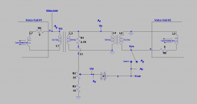
Here's how the system described in the attached schematic works. Each voice coil is shown as an 8 Ohm resistor in series with a certain inductance. Let's begin with voice coil #1 at the left part of the schematic:
1. An arbitrary vacuum is presented to the surface of the cone. It pulls it a certain distance forward or out of the enclosure towards the observer..
2. The voice coils are attached to the cone. The motion of the cone generates an output electrical signal [Vis] which is depicted as the rising part of a sine wave. It is acting like a microphone.
3. The voltage [Vis] is stepped up in the left transformer to get Vp. Vp is next attenuated via the resistor ladder for presentation to the non-inverting input of the power amp which has a voltage gain = 27.
3. The power amp's output voltage [Vout] is in phase with the output signal Vos at the 25.2 Vac winding of the right transformer which is loaded by voice coil #2.
4. As an example, Vout of the power amp was made equal to Vis [in a prior tweaking step] by adjusting the level control pot [25 Ohm] at its input.
5. Close the switch at Vout. The rising signal at Vout across voice coil #2 pushes the cone forward or out of the enclosure. This "push" generates a rise in pressure at the cone's surface which nulls or attenuates the vacuum which had been imposed on it. The cone does the second duty of a normal woofer
6. The cone must continue to move in the same direction as that originally imposed on it by the vacuum. It must not sit still; as it'll behave like a wall surface.
7. All of the depicted sine signals in the schematic are in phase. A positive voltage feedback [PVF] loop around the power amp is explicit.
8. One can also use an arbitrary rise in pressure at the cone surface instead of a vacuum. The cone is asked to move towards the inside of the enclosure. This disturbance is simultaneously augmented by the power amp which actively pulls in the cone via voice coil #2; keeping it moving in the same direction effected by the stimulus. A consequent vacuum thus emerges at the cone's surface to null or attenuate the offending original pressure stimulus.
I'll show the steps to tweak this system in the next post.
Attachments

Last edited:
This inspired me to think of how to increase the negative output impedances even more, way beyond normal oscillation. You could build an amp with minus 100 ohm output impedance that would sense and correct in the same way with only one voice-coil.
The problem that arises is unstability. The amp would oscillate with vigor if nothing is done to stop the oscillation.
This problem is already solved within radio circuitry. It is called a super-regenerative receiver. In a pure regenerative receiver you increase the sensitivity by applying positive feedback into the resonant tuning circuit until very close to oscillation. In a super-regenerative receiver you let it oscillate - BUT - every once in a while before the oscillation gets to strong you short the resonant circuit with a quenching frequency to stop the oscillation dead short. This quenching frequency must be above the audio band - or - in a subbwofer amp as in your example above, it could be filtered away.
I understand this only at a very superficial theoretical level, but I immediately recognized the similarity between your application and the problem Armstrong solved by allowing the resonant circuit to partly resonate to increase gain many times over.
designing superregenerative receivers
Cheers,
Johannes
Thanks Johannes, you are the first to suggest any way of adding positive current feedback to the F6. When you say "add a .5 ohm power resistor between speaker and ground" I assume you mean from the out point of the amplifier to ground.
No, he meant it as he said it. The 0.5R senses the current through the speaker and thus is a form of current feedback.
Jan
Thanks Johannes for the article on designing superregenerative receivers, for briefly explaining their works, and the ideas you presented. It is appealing to use a single woofer like in US 4,899,387, and especially to use a single transistor [per examples in the article] to do the job instead of the oversized amp I'm using.
Thanks to Jan for the post above which mentioned F6. It made me recall that mikegranger had also talked about regenerative receivers in post #232 of the thread First watt F7 review.
Cleaning the listening room from standing waves will improve the subjective performance of the power amp just built and quickly tested with music in the same room.
Thank you Antoniel for sharing your ideas, experiments and results you get with different forms of feedback. This is very interesting.
Cheers
Johannes
Cheers
Johannes
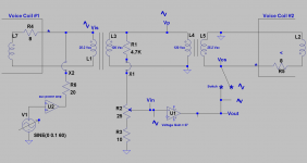
The attached schematic was used to adjust/tune the system shown in post #91. The bottom left view shows a sine signal generator with an adjustable output level feeding an auxiliary power amp. This amp's power output was sent to Voice Coil #1 via a 20 Ohm power resistor. It energized coil#1 so as to simulate exposure to a signal from a standing wave [sw]. Here's the process:
1. Minimize the 25 Ohm pot at the input of power amp with positive voltage feedback [call it A; Vg =27].
2. Open switch at the output of power amp A.
3. Send a power output signal [60 Hz] to Voice coil #1. Its level was measured with an AC multimeter; say equal to 30 mV. The subwoofer hummed.
4. Dial up the 25 Ohm pot such that Vout of power amp A is ~30 mV.
5. Close switch at at Vout of power amp A so as to connect it to Voice Coil #2.
6. Measure the voltage drop across VC1, and fine tune its level to a minimum of 30 mV. This is bootstrap condition. The loudness of the audible hum did not change much.
7. An SPL meter registered ~1/2 dB drop when VC2 was energized; at a distance of ~1 foot from the cone of the woofer.
8. VC2 had a lower voltage drop across it relative to 30 mV. It was adjusted up to that value with the 25 Ohm pot.
9. The adjustment made in point 8 also increased the voltage drop across VC1.
10. In general, the initial stimulus voltage drop across VC1 of 30 mV was readily increased to 60 -75 mV by dialing up further the 25 Ohm pot. There's clearly positive voltage feedback around power amp A
11. System stayed stable. But a nuisance 60 Hz signal grew in amplitude to 20 mVp-p [on scope] without a stimulus signal to VC1.
12. Any further increase of voltage drop across VC1, showed signs of a low frequency oscillation. It seemed to me that the oscillator piggy-backed on the stimulus signal by reproducing it.
NB:
1. Still a difficult system to work with. It is not as effective in suppressing standing waves like that patented by Mr. Pass. He recorded a minimum 6 dB decrease in SPL. I recorded this same behavior of this DVC sub system [drop ~1/2 dB] in the older thread of this subject entitled: diy US 4,899,387.
2. A cut of music rich with low bass sounds different with and without the system engaged.
I have one more schematic to show with a bit of analysis.
Attachments
Perhaps there is some confusion. I have been talking about positive current
feedback, not positive voltage feedback and in this case proper implementation
lowers the output impedance at the cost of slightly higher distortion.
For the F7, about 2 dB of positive current feedback can lower the output
impedance by factor of 30 or greater. You could not achieve that with
ordinary negative feedback unless you were to increase the feedback by
about 30 dB.
😎
There appears to be two different uses of the term Current Feedback:
- feedback of the sensed current of the speaker load.
- feedback of the sensed output voltage across the speaker load into low impedance node of the input stage.
There appears to be two different uses of the term Current Feedback:
I prefer use #1, but too often we see #2 described as current feedback. Isn't there a better term to describe use #2?
- feedback of the sensed current of the speaker load.
- feedback of the sensed output voltage across the speaker load into low impedance node of the input stage.
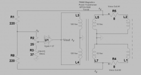
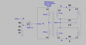
Hello lhquam. I've been experimenting with the symmetrical system of the left schematic. It interferes with sound in the room corner. It may fit #2; but I'm unsure, so I'd call its feedback voltage instead of current.
The right schematic [not tested; just written] is most probably #1 or using current feedback.
Note the transformer is now a single power toroid; instead of 2 shown in a past post. This symmetric approach does not distinguish one voice coil as a mic, and the other as a driver.
I will show the detailed schematic of the left system which includes tuning etc..
Attachments
Hello lhquam. I've been experimenting with the symmetrical system of the left schematic. It interferes with sound in the room corner. It may fit #2; but I'm unsure, so I'd call its feedback voltage instead of current.
The right schematic [not tested; just written] is most probably #1 or using current feedback.
Note the transformer is now a single power toroid; instead of 2 shown in a past post. This symmetric approach does not distinguish one voice coil as a mic, and the other as a driver.
I will show the detailed schematic of the left system which includes tuning etc..
Where are the inputs?
In the left circuit the feedback is the voltage(s) sensed across the load, thus making it (positive) voltage feedback.
The right circuit shows (positive) current feedback.
In post #97 the 2nd use of the term "current feedback" I was referring to was voltage feedback into a low impedance node of some form of difference amplifier, such as the source node of the F5 JFET stage. Texas Instruments has an Application Report about this type of "current feedback": http://www.ti.com/litv/pdf/sloa066.
Thanks lhquam for the ti link, and your clarification.
Where are the inputs. Each voice coil is a dynamic microphone [input], and an output driver. Here's how it works for the attached circuit with PVF during music play from an independent stereo loudspeakers inundating the room with sound waves.
1. Let the cone of the DVC subwoofer be pulled out of its enclosure from a sound wave with a vacuum characteristic.
2. The resultant rising positive output signal from each voice coil [depicted], is sent to the power amp via the 220 Ohm resistors.
3. The two signals are summed at the top of the 25 Ohm pot which feeds the non-inverting port of the power amp.
4. The output [Vout] of the power amp is stepped down; such that it generates in each voice coil an in-phase power signal of equal amplitude to the parent which induced it in the first place.
5. Here is the net value: The power amp enables the cone to become "more compliant" relative to a state of its non-involvement. Thus, it easily pushes the cone out to generate a positive pressure [by convention]. This positive pressure adds acoustically to the vacuum from the parent stimulus and diminishes it in real time.
6. Thus, the energy of the parent sound wave was diminished by this destructive interference.
I have more to expand on the above in my next post.
.
.
Attachments

- Status
- Not open for further replies.
- Home
- Amplifiers
- Pass Labs
- Experimenting with Positive Feedback