BTW Here is an appetizer 😉
Where is the pfb, where the nfb?
Here's the whole article. 1950 guys!
http://linearaudio.nl/sites/linearaudio.net/files/miller combined fb electronics march 1950.pdf
Jan
Where is the pfb, where the nfb?
Here's the whole article. 1950 guys!
http://linearaudio.nl/sites/linearaudio.net/files/miller combined fb electronics march 1950.pdf
Jan
Attachments

Last edited:
Current positive feedback can be easily implemented :
http://www.diyaudio.com/forums/mult...ear-their-resonant-frequency.html#post1786574
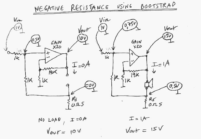
Without current in shunt Rs, the amp input voltage is divided by almost 2.
When there is some voltage across Rs, the amp input voltage is increased by the bootstrap action (positive feedback).
So the whole circuit has more voltage gain at the frequencies where the driver has low impedance and less voltage gain around its resonance.
The apparent Q of the driver is lowered.
Beware that the inductive component of the voice coil resonates with the capacitive component of the motional impedance.
http://www.diyaudio.com/forums/mult...ear-their-resonant-frequency.html#post1786574
Without current in shunt Rs, the amp input voltage is divided by almost 2.
When there is some voltage across Rs, the amp input voltage is increased by the bootstrap action (positive feedback).
So the whole circuit has more voltage gain at the frequencies where the driver has low impedance and less voltage gain around its resonance.
The apparent Q of the driver is lowered.
Beware that the inductive component of the voice coil resonates with the capacitive component of the motional impedance.
BTW Here is an appetizer 😉
Where is the pfb, where the nfb?
Here's the whole article. 1950 guys!
http://linearaudio.nl/sites/linearaudio.net/files/miller combined fb electronics march 1950.pdf
Jan
Thanks jan.didden for the link.
Last edited:
It is curious that page #5 of one of the most known documents is so rarely quoted. It deals with negative output impedance applied to loudspeakers (by the way, with it, the concept of damping factor is questionable) :
http://www.northreadingeng.com/A_N_Thiele_Vented_Part_II.pdf
http://www.northreadingeng.com/A_N_Thiele_Vented_Part_II.pdf
You can manipulate the Zout to get the effect you want. Morgan Jones' Arpeggio speaker requires a resistance in series with the amp output of 6 ohms IIRC to get the designed-for damping. It's all engineering, nothing magical.
Jan
Jan
Can safely operate at a 90% extent PFB relative to 100% NFB.
Thanks for that info.
Hope this thread continues.
I'd like to build something w/ adjustable PFB to hear the sonics...
It is curious that page #5 of one of the most known documents is so rarely quoted. It deals with negative output impedance applied to loudspeakers (by the way, with it, the concept of damping factor is questionable) :
http://www.northreadingeng.com/A_N_Thiele_Vented_Part_II.pdf
Thank you forr for this document.
I'd like to build something w/ adjustable PFB to hear the sonics...
I've built exactly that, so it is certainly possible.
BTW Here is an appetizer 😉
Where is the pfb, where the nfb?
Here's the whole article. 1950 guys!
http://linearaudio.nl/sites/linearaudio.net/files/miller combined fb electronics march 1950.pdf
The vacuum tube amp used Negative Feedback, and Positive Voltage Feedback. My amp understudy uses both of the aforementioned types of feedback. Thus it gives/has performance benefits that can be like those reported by the authors. And this is great news.
It's all engineering, nothing magical.
And simulators can easily model it.
When you think about it, the notion of whether the feedback is voltage or
current depends only on what differential voltages you are looking at -
output / ground for voltage feedback and current sense for current feedback.
Generalized a bit you see local positive current feedback in such circuits as
mu followers and Alephs, with a small amount (typically 6 dB).
Also in "dynamic bias" and Cordell's error correction circuit where the current
induced voltage drop between the drive and output in a follower stage is
sensed and dealt with locally.
😎
Fully agree Nelson. Cordells error correction (Hawksford kind) as well as my own experiments in the paX amp are based on positive feedback. Not familiar with those others you mention but I have an idea how that would work.
Actually I took out a Dutch patent on an error correction scheme, many years ago, which made me very proud, until someone at an AES convention pointed out to me that it was based on a combination of PFB and NFB first described by a guy named Welwyn about 1920 or thereabouts...
You live and learn.
Jan
Current positive feedback can be easily implemented :
http://www.diyaudio.com/forums/mult...ear-their-resonant-frequency.html#post1786574
Without current in shunt Rs, the amp input voltage is divided by almost 2.
When there is some voltage across Rs, the amp input voltage is increased by the bootstrap action (positive feedback).
So the whole circuit has more voltage gain at the frequencies where the driver has low impedance and less voltage gain around its resonance.
The apparent Q of the driver is lowered.
Beware that the inductive component of the voice coil resonates with the capacitive component of the motional impedance.
Hello forr. Thanks for the schematics. I will use them to experiment with Positive Current Feedback [PCFB] as part of this thread. And maybe later on use NFB, PVFB and PCFB simultaneously in the amp.
Last edited:
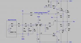
The attached schematic details the following changes:
1. The output stage of the power amp is made up of independent bjts which assemble 2 complementary Darlingtons. Positive Voltage Feedback [Vo''] is shown to emanate from the emitter of the first NPN bjt in Darlington. It can also start at the emitter of its complement.
2. Vo'' can also be the power output Vo. I chose the indicated Vo'' so as to distance it from the loudspeaker interface which is solely dedicated to NFB.
3. Note the value of the Positive Voltage Feedback [PVFB] resistor is 47 K which is the same value as that for NFB.
4.The 47 K PVFB resistor must be terminated to common with an equivalent resistance of less than 1.8 K which is the value of the resistor at the inverting port of the diff amp.
5. As I slowly and carefully increased the value of the 1K resistor, the scope at Vo showed the birth of the imminent and possible oscillating signal [50-60 Hz].
6. I purposely exceeded 1.8 K equivalent resistance at the non inverting port. The power amp was stable without load, and loaded with an 8 Ohm power resistor. The amp's special fuses immediately blew when I attempted to connect the loudspeaker which shrieked, and scared my %&#*.
In the previous schematics, PVFB started at Vo' which is a high impedance port and terminated in a summing junction. It may be called Schade PVFB akin to Schade NFB.
I'll show in the next post the scheme I am using to safeguard the system from damage due to oscillation.
Attachments
Very interesting ...how probable is it to implement in an old hk receiver? It currently has about .25% hd
Also on what order magnatude % wise will it lower distortion?
Do you believe there would be any real gains by this?
Thanks
Lawrence
Also on what order magnatude % wise will it lower distortion?
Do you believe there would be any real gains by this?
Thanks
Lawrence
I think that's because the stage which is linearised by the error correction usually has an initial voltage gain less than unity. Otherwise it would be negative feedback but the error correction mechanism would work as well. This happened with a null signal at the input and some voltage at the output, coming by example from the voice coil moving in the gap due to external sound pressure.Cordells error correction (Hawksford kind) as well as my own experiments in the paX amp are based on positive feedback.
Hello forr. Thanks for the schematics. I will use them to experiment with Positive Current Feedback [PCFB] as part of this thread. And maybe later on use NFB, PVFB and PCFB simultaneously in the amp.
Hi Antoinel,
I suggest you experiment all these using well known sturdy IC power package and, if possible, a dual regulated power laboratory supply with a settable current limit.
Very interesting ...how probable is it to implement in an old hk receiver? It currently has about .25% hd
Also on what order magnatude % wise will it lower distortion?
Do you believe there would be any real gains by this?
Thanks
Lawrence
The link to the article in post #41 by jan.didden has positive answers to your questions. Post #23 adds findings [to the author's article] which have value. I believe that real gains and value with minimum detriment are possible.
Hi Antoinel,
I suggest you experiment all these using well known sturdy IC power package and, if possible, a dual regulated power laboratory supply with a settable current limit.
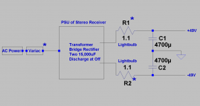
Thanks forr for your advice. I have been using the approach in the attached schematic to safeguard the system. It was adequate, and predicted oscillation; provided the changes in the resistor values in the PVFB circuit were small, and Vout was monitored on the scope for the birth of oscillation.
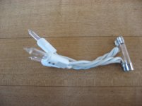
1. The essential components are the variac, and the light bulb fuse which I show in the adjacent photo.
2. The light bulb fuse uses 1-3 X-mas light bulbs which are soldered across a blown regular fuse. Each light bulb can handle up to 120 mA before it blows.
3. Under stable operating conditions, each light bulbs glowed faintly; handling the ~80 mA idle current per power rail.
4. On start up, and without a load at Vout, increase the voltage of the variac as one eyes the light bulbs. A problem will exist if the lights get brighter, stay bright, and/or blow. The problem must be resolved.
5. Idle the stable amp for a time. Connect an 8 Ohm load power resistor.
6. Disconnect the power resistor. Carefully and slowly connect the loudspeaker.
7. The system is safe if the extent of PVFB is a maximum of ~80-90% the value of NFB. This extent is basically the ratio of the equivalent resistance/impedance at the non-inverting input to 1.8 K at the inverting input of the diff amp.
8. Oscillation is assured and sudden at the ratio of PVFB/NFB=1 or higher. This blows the light bulbs, and is heard loud and clear from the loudspeaker.
Attachments
- Status
- Not open for further replies.
- Home
- Amplifiers
- Pass Labs
- Experimenting with Positive Feedback