Any design should cover all possible conditions of use. Even turning the Sony off could 'raise' the impedance seen at its output terminals.
A good design has to be foolproof.
+10
It's hard enough to make anything foolproof - fools are rather ingenious ;-)
'Murphy' comes to mind.
Jan
My ignore list is at 3 people at the moment.
2 of the 3 have a chance of making their way off the list but the other one is a life time hall of fame member on the ignore list. Hahahahaha
Am I off yet? Forgive and forget I always say. I do admire your talents and your experimentation's and try to learn from what you are doing.
🙂
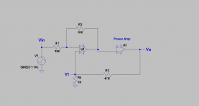
The attached schematic shows the following:
1. I added the resistor values for the diff and LVA amps; so as to simplify LTspice sims.
2, The PFB, and NFB resistors are each 47 K.
3. The equivalent resistance to ground at the (+) input is equal to 1.5 K, versus 1.8 K at the (-) input.
4. This amp is stable against oscillation; due to a slight and net excess of NFB over PFB as noted in a previous post.
2. The small and larger numbers [boxed] for Vin, Vo' and Vo were measured at a test frequency of 100 Hz with an AC DMM before and post PFB respectively.
I think the following conclusions have value.
1. The power amp behaved as an in-situ preamp by amplifying Vi by ~a factor of 4.
2. The post PFB signal Vo' becomes a part of the feedback loop of the generator, and/or an input buffer. Note the increase in the voltage drop across the 10 K resistor in series with the generator's signal output with PFB. It means that the headphone amp and/or an independent post buffer helps clean up Vo' with the power amp's NFB.
3. May consider a current source preamp instead of the voltage source buffer to negate point 2.
I am looking forward to the next schematic and its results at ~equal PFB and NFB.
Attachments

I think you mix up a few things. The input signal is greatly attenuated, that is why you see such low gain overall. The amp has a gain of about 20 as set by the NFB but because you attenuate the input signal you throw away a factor of 5 almost.
The PFB doesn't 'clean up' anything. Properly implemented, PFB increases loop gain so the NFB has more effect and therefore the distortion drops.
The only effect you should see when switching PFB on or off is a drop in distortion and possibly a slight rise in gain.
Jan
The PFB doesn't 'clean up' anything. Properly implemented, PFB increases loop gain so the NFB has more effect and therefore the distortion drops.
The only effect you should see when switching PFB on or off is a drop in distortion and possibly a slight rise in gain.
Jan
Last edited:
You should heed rule one of research: change one thing at the time.
My suggestion of a buffer was not just for fun.
If you really want to know he effects of the PFB, put an opamp in front, Vin to one input, PFB to the other. You then have a regular 20x NFB amp with switchable PFB.
When using the PFB switch, nothing else changes and you get a clear picture of what it is that the PFB does.
Jan
Thanks jan.didden for your advice. I'll rearrange the input circuit to the power amp so as to include a buffer, and report results.
You will find that PFB is a very powerful technique, much neglected.
I would put an inverting opamp stage, gain = 1 with Vin into the inverting input through say 10k with a 10k from it's output to inverting input. Then the PFB divider 68k and 1k into the non-inverting input. That way, the 1k provides the bias and the 68k can be switched on or off with no other changes. Don't worry about offset - you are interested in the PFB right now.
Jan
I am testing this with a input transofrmer and ACA . The Xformer is connected to the ACA via the inverting output . The ACA is exactly as it is in the original schematic , with negative feedback and buffer . Then from the output of the ACA , which is non inverting this time with respect to the Xformer , I put a positive feedback loop to the non invertin Xfromer input . Very interesting .You will find that PFB is a very powerful technique, much neglected.
I would put an inverting opamp stage, gain = 1 with Vin into the inverting input through say 10k with a 10k from it's output to inverting input. Then the PFB divider 68k and 1k into the non-inverting input. That way, the 1k provides the bias and the 68k can be switched on or off with no other changes. Don't worry about offset - you are interested in the PFB right now.
Jan
Can you give more details?
Yes , sure .
I will post a schematic so we can discuss ....
You will find that PFB is a very powerful technique, much neglected.
I would put an inverting opamp stage, gain = 1 with Vin into the inverting input through say 10k with a 10k from it's output to inverting input. Then the PFB divider 68k and 1k into the non-inverting input. That way, the 1k provides the bias and the 68k can be switched on or off with no other changes. Don't worry about offset - you are interested in the PFB right now.
Jan
Thanks jan.didden for your suggested [attached] schematic. I've also used the power amp's output node Vo instead of its internal Vo' as the generator of PFB with equal or better results. Vf is the sole variable by changing the value of the 1 K resistor.
Attachments
Good circuit, but where is the NFB?? Should there be an NFB from Vout to inv input of the amp?
Jan
Jan
I think you mix up a few things. The input
signal is greatly attenuated, that is why you see such low gain overall. The
amp has a gain of about 20 as set by the NFB but because you attenuate
the input signal you throw away a factor of 5 almost.
The PFB doesn't 'clean up' anything. Properly implemented, PFB
increases loop gain so the NFB has more effect and therefore the distortion drops.
The only effect you should see when switching PFB on or off is a drop in
distortion and possibly a slight rise in gain.
Perhaps there is some confusion. I have been talking about positive current
feedback, not positive voltage feedback and in this case proper implementation
lowers the output impedance at the cost of slightly higher distortion.
For the F7, about 2 dB of positive current feedback can lower the output
impedance by factor of 30 or greater. You could not achieve that with
ordinary negative feedback unless you were to increase the feedback by
about 30 dB.
😎
Good circuit, but where is the NFB?? Should there be an NFB from Vout to inv input of the amp?
Jan
Maybe the attached circuit is the one.
Attachments

Danger, Will Robinson!
😎
Will Robinson experienced the wrath of oscillation from ~equal extent of positive and negative voltage feedback presented to the diff amp. The power rail fuses lit up the room in a flash but the test power amp is still OK.
The power rail fuses lit up the room in a flash
Hey...somebody's got to test it out...😀
Can safely operate at a 90% extent PFB relative to 100% NFB. The findings in post 23 highlight the value Positive Voltage Feedback [PVFB] adds to performance.Hey...somebody's got to test it out...😀
Perhaps there is some confusion. I have been talking about positive current
feedback, not positive voltage feedback and in this case proper implementation
lowers the output impedance at the cost of slightly higher distortion.
For the F7, about 2 dB of positive current feedback can lower the output
impedance by factor of 30 or greater. You could not achieve that with
ordinary negative feedback unless you were to increase the feedback by
about 30 dB.
😎
OK, yes, I see. I was not considering that; rather the mix of pos and neg feedback to artificially increase loop gain for lower distortion (and also lower output impedance). Your use is more elegant, I admit.
Jan
- Status
- Not open for further replies.
- Home
- Amplifiers
- Pass Labs
- Experimenting with Positive Feedback