This datasheet http://cds.linear.com/docs/Datasheet/1964fb.pdf is one of the few who address ceramic capacitors problem.
From page 12-13:
¨Voltage and temperature coefficients are not the only
sources of problems. Some ceramic capacitors have a
piezoelectric response. A piezoelectric device generates
voltage across its terminals due to mechanical stress,
similar to the way a piezoelectric accelerometer or microphone works.
For a ceramic capacitor the stress can be
induced by vibrations in the system or thermal transients.
The resulting voltages produced can cause appreciable
amounts of noise, especially when a ceramic capacitor is
used for noise bypassing. A ceramic capacitor produced
Figure 4’s trace in response to light tapping from a pencil.
Similar vibration induced behavior can masquerade as
increased output voltage noise.¨
Now some arithmetic's.
You have a 2V output dac which is 24bit resolution.
This mean you have 16777216 steps.
Each step is only 119 nano Volts.
An 100nF X7R multilayer cap will give approx 100uV at a very tiny tapping.
One solution is to mount these caps on one side, but as I stated above, use silver-mica even these are more expensive, or at least NP0.
Regards,
Tibi
Last edited by a moderator:
I want one board!The PCB was $5, CS4398 $13, caps/dipswitch/pins about $7, so it cost ahem 1/4 the price of the DAC I have a few spare blank pcb's if anyone wants.
Can you tell what the values on the caps should be?
Edit:The dip switchs is it a standard one or do I have to ues a special one?
Last edited:
Even 1nH is a huge inductance and using a scope, I found only ceramics will deal with the HF. Through-hole capacitors have a too much lead inductance ~8nH. So far, bigger is better works with MLCC caps >>1uF giving the lowest measured noise+HF ripple.
I'll try staggered values like Boky suggested, and add small ESR to if damping ringing is worth the hassle. Maybe should start a new thread on this because it applies to all delta-sigma DAC IC's.
I'll try staggered values like Boky suggested, and add small ESR to if damping ringing is worth the hassle. Maybe should start a new thread on this because it applies to all delta-sigma DAC IC's.
These are SMD mica capacitors.
MC22FD102J-F Cornell Dubilier Mica Capacitors
Try just only one 1nF to decouple ASRC oscillator and you´ll be amazed by the result.
Indeed ceramic capacitors offer lower ESR, but this is only for a very tight frequency range.
Beside temp stability, non piezo efects, extremely low capacitance variation with voltage, mica dielectric retains its high-Q to a wider megahertz range.
IMHO stacking ceramic caps in the hope that will hit the problem is not a solution.
Regards,
Tibi
Last edited by a moderator:
I tried CDE 1000pF mica with short leads and FFT showed it attenuates the higher harmonics better but the ESR is too low, the waveform has a lot of ringing.
I tried CDE 1000pF mica with short leads and FFT showed it attenuates the higher harmonics better but the ESR is too low, the waveform has a lot of ringing.
Sorry if I was not clear.
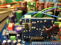
My recommendation was to decouple only ASRC oscillator with silver mica, as per attached picture.
I do not recommend to decouple any analog circuit with mica.
For analog you may use polypropylene, polyester smd capacitors, or small values 1n up to 10n CG0 ceramic.
Regards,
Tibi
Attachments
These are SMD mica capacitors.
MC22FD102J-F Cornell Dubilier Mica Capacitors
Try just only one 1nF to decouple ASRC oscillator and you´ll be amazed by the result.
Indeed ceramic capacitors offer lower ESR, but this is only for a very tight frequency range.
This is why I told you the parallel solution of 100nF, 22nF and 1nF produces excellent results. Even if X7R is suspect to piezoelectric effect, they still sound great in combination I stated – no one’s going to tap on them with the pencils anyway…. The npo dielectric sounds softer, less defined + there is a change in sound character over time with npo dielectric, as the whole board and inclosure get warmer, that I can hear clearly.
Beside temp stability, non piezo efects, extremely low capacitance variation with voltage, mica dielectric retains its high-Q to a wider megahertz range.
Will you stop already with silvered-mica caps? They sound terrible!
IMHO stacking ceramic caps in the hope that will hit the problem is not a solution.
What hope? Haven’t I already stated clearly that I could measure the noise results at supply pins?
Regards,
Tibi
Sorry if I was not clear.
My recommendation was to decouple only ASRC oscillator with silver mica, as per attached picture.
I do not recommend to decouple any analog circuit with mica.
For analog you may use polypropylene, polyester smd capacitors, or small values 1n up to 10n CG0 ceramic.
Regards,
Tibi
tvicol
I did this too to the ASRCboard but with a MKP film. The result is quite unsure since there's not much improvement heard but sometimes I think bass is bit more improve...I guess 😕
This is why I told you the parallel solution of 100nF, 22nF and 1nF produces excellent results. Even if X7R is suspect to piezoelectric effect, they still sound great in combination I stated – no one’s going to tap on them with the pencils anyway…. The npo dielectric sounds softer, less defined + there is a change in sound character over time with npo dielectric, as the whole board and inclosure get warmer, that I can hear clearly.
Will you stop already with silvered-mica caps? They sound terrible!
What hope? Haven’t I already stated clearly that I could measure the noise results at supply pins?
Used in the right place mica can improve things a lot.
I guess you performed your measurements in a place where is no vibration. Unfortunately things are going complicated in an environment where musing is playing.
Put your board over a speaker while this is playing music and perform same measurement. Tell us the result here.
Regards,
Tibi
Last edited by a moderator:
tvicol
I did this too to the ASRCboard but with a MKP film. The result is quite unsure since there's not much improvement heard but sometimes I think bass is bit more improve...I guess 😕
Please do not generalise, each capacitor must be used where his effect is maximum.
In that place, if you want results, use 1nF silver-mica.
Based on the dielectric and construction each capacitor have his own application range.
An MKP will not do to much in that position.
Regards,
Tibi
Last edited by a moderator:
Please do not generalise, each capacitor must be used where his effect is maximum.
In that place, if you want results, use 1nF silver-mica.
Based on the dielectric and construction each capacitor have his own application range.
An MKP will not do to much in that position.
Regards,
Tibi
Is 1nF is the absolute value for silver mica??? I have some 220pF and 330pF silver mica in my drawer. You think those value worth a try???
Is 1nF is the absolute value for silver mica??? I have some 220pF and 330pF silver mica in my drawer. You think those value worth a try???
You can give them a try, but for audible effect you should go for 1nF up to 2,2nF.
These will clear highs, better separation, better soundstage and focus, less jitter in ASRC oscillator.
Regards,
Tibi
You can give them a try, but for audible effect you should go for 1nF up to 2,2nF.
These will clear highs, better separation, better soundstage and focus, less jitter in ASRC oscillator.
Regards,
Tibi
ok will try.
i have good experience with silver mica in my amplifier at feedback section. might try this as well.
Is there a big sound advantage with using the cs8xxx chips with transformer coupled output vs the pcm1xxx chips with quality op amps?
I tried 1000pF mica on the ASRC oscillator- looking with my scope it totally cleans up the noise on oscillator Vcc. I didn't hear any audible change but have to give it a good listen.
Hi everyone.
I've been in the process of building / completing my JLH amp for quite som time now. The project was ment to refresh my knowledge (or lack thereof) about electronics, but seeing all the diy kits flying around all over, it didn't happen. Anyways, the amp itself is nearing completion, all that's left is to add a regulated psu, softstart and a DAC.
I bought this DAC from Gigaworks and it arrived today. I've read trough this thread but it's 386 pages long so i'm granting myself the liberty to ask if i need / will benefit from this mod on this DAC even.
New 24/192 DAC DA CONVERTER CS8416+CS8421+CS4398 USB - eBay (item 120702682594 end time Jun-21-11 22:49:39 PDT)
I should probably have been able to spot it and answer that myself, but i'm too far behind on experience / knowledge i am afraid.
Anyone else tried this DAC? Any problems playing 192Khz files? (or any problems at all for that matter 😛)
Sincerely
Ben.-
Just wondering if anyone tried this monster? DAC TDA1541, AD1865, AD1955, PCM63, CS4398 series | eBay
Hello there,
I own the old version of the Gigaworks DAC:
New 24/192 DAC DA CONVERTER CS8416+CS8421+CS4398 USB | eBay
You can see it in the third picture, some people here have built the same version or the very similar version that was sold before.
I wonder if anyone made it possible to switch the input from the outside of the enclosure? In this version the inputs can only be changed by using the jumpers.
Any1 got an idea how to do that?
Hello there,
I own the old version of the Gigaworks DAC:
New 24/192 DAC DA CONVERTER CS8416+CS8421+CS4398 USB | eBay
You can see it in the third picture, some people here have built the same version or the very similar version that was sold before.
I wonder if anyone made it possible to switch the input from the outside of the enclosure? In this version the inputs can only be changed by using the jumpers.
Any1 got an idea how to do that?
Carefully solder switches to the jumper pins. You can use old jumpers to solder on so you dont have to solder directly on the DAC.
I saw someone posting schematics on how to solder a few pages back i think.
- Home
- Source & Line
- Digital Line Level
- Experience with this DIY DAC ?