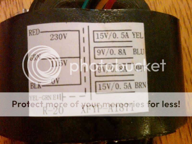
can you take a pic of the trans your using? green is usually the ground
On this transforner the green wire is actually one of the AC inputs (wired as neutral here). The green/yellow is the ground/shield.
There is a reason why im asking, because I don't no anything about this stuff but im smart enough to ask because i know i can die.
It came soldered like that.
So, I put a screw through the chassis connected to a wire that will be soldered to the yellow/green wire at the base of the outlet? And then I wrap all those with electrical tape and dont ever touch those right?
It came soldered like that.
So, I put a screw through the chassis connected to a wire that will be soldered to the yellow/green wire at the base of the outlet? And then I wrap all those with electrical tape and dont ever touch those right?
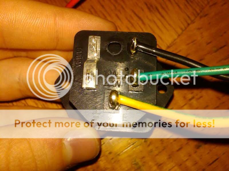
I know what the ground symbol is, I was thrown off by line intel ground, and there is an "L" on the back of that thing with a spot for a wire... I take it the power line intel is the plastic thing im holding?
I saw your in USA so 110 is good ,try it with out the wire to the pan ,if it hums then hook it up ,make sure no metal parts wires ect touch the pan,use nylon spacers under the board,if your not sure get someone to help you that does know no need to fry it or you!
the plug has a fuse in it so the black wire runs through the fuse to L thats one side of the ac line ,the green is the other lug, pop the fuse out and maybe you can see how it's made ,a little confusing isn't it! looks like your good the way it's connected ,
Can I try it like this?
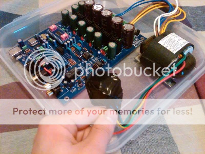
Its on the plastic lid, and a wrapped the back of the inlet with a lot of electrical tape
Its on the plastic lid, and a wrapped the back of the inlet with a lot of electrical tape
looks ok do put some tape on the end of the unused red wire, what input are you going to use?
You should be OK to test it like that. Just make sure the power cord is plugged into that IEC socket BEFORE you plug it into the wall. Don't grab the IEC socket to plug/unplug the power cord while it's plugged into the wall.
Watch the end of that red wire though, there will be mains AC voltage on the end of it.
Watch the end of that red wire though, there will be mains AC voltage on the end of it.
Edcor
.
EDCOR Electronics Corporation. MXL8cs
.
EDCOR Electronics Corporation. XSM600/10K
.
http://www.jensen-transformers.com/datashts/11emcf.pdf
I have some Edcor transformers MXL8CS at 1:8 that I use for I/V, and the big XSM at 1:4 that they sell for $13 which are an amazing value if you need something that big. I bought those to use for a cheap trial with 1794a someday. I haven't tried any of Edcors at 1:1. Since you only need two for a dac, I would go with the Jensen JT-11-EMCF for $50 to get into an 80% nickel core. They sound excellent. If it was for six channels in a crossover I might be tempted to play with something cheaper but for two channels it is worth it to spring for something really nice.has anyone used the output trans from edcor as outputs from the dac?
good..... bad ??????
.
EDCOR Electronics Corporation. MXL8cs
.
EDCOR Electronics Corporation. XSM600/10K
.
http://www.jensen-transformers.com/datashts/11emcf.pdf
I haven't tried any of Edcors at 1:1.
The XS440 looks like one worth trying. Nice frequency response, but they don't give any mention of the input/output impedance.
EDCOR Electronics Corporation. XS4400
this thread deals with Vout dacs
I don't know why anyone want to use out transformer (the quality tx Is expensive)
here Is very interesting thread http://www.diyaudio.com/forums/digital-source/42441-out-stage-sony-cd-players-5.html how to build discrete output stage using jfets
there Is a schematic which allows to get rid of coupling cap http://web.archive.org/web/20070219232819/http://perez.r.free.fr/XB_out_fet_dc_0v.JPG
It Is for sony xb940 but I think It can be used with Vout dacs like wm8740, cs4397/8
The XS440 looks like one worth trying. Nice frequency response, but they don't give any mention of the input/output impedance.
EDCOR Electronics Corporation. XS4400
The Impedance will be a reflection of whatever it is hooked up to, in parallel with its open circuit impedance which is always in the many thousands of ohms, 150k or so. They are like mirrors.
The listed rating, when there is one, is the load that it can drive and still meet specs. If the load is higher numerically, the performance will be higher also.
.01% distortion @1Khz is not very good for a trafo, at lower hz it will be several magnitudes higher.
this thread deals with Vout dacs
I don't know why anyone want to use out transformer (the quality tx Is expensive)
here Is very interesting thread http://www.diyaudio.com/forums/digital-source/42441-out-stage-sony-cd-players-5.html how to build discrete output stage using jfets
there Is a schematic which allows to get rid of coupling cap http://web.archive.org/web/20070219232819/http://perez.r.free.fr/XB_out_fet_dc_0v.JPG
It Is for sony xb940 but I think It can be used with Vout dacs like wm8740, cs4397/8
There are several very good reasons to use trafos. The top one is, they sound great.
They eliminate the DC offset voltage from the dac chip outputs, eliminating the need for coupling caps.
They supply a certain amount of ultrasonic filtering.
They supply you with a differentially balanced output which is great if your other components are balanced, as mine are.
Borrow a couple from someone and try it before you knock it.
- Home
- Source & Line
- Digital Line Level
- Experience with this DIY DAC ?